background image

6 Powering Up and Down

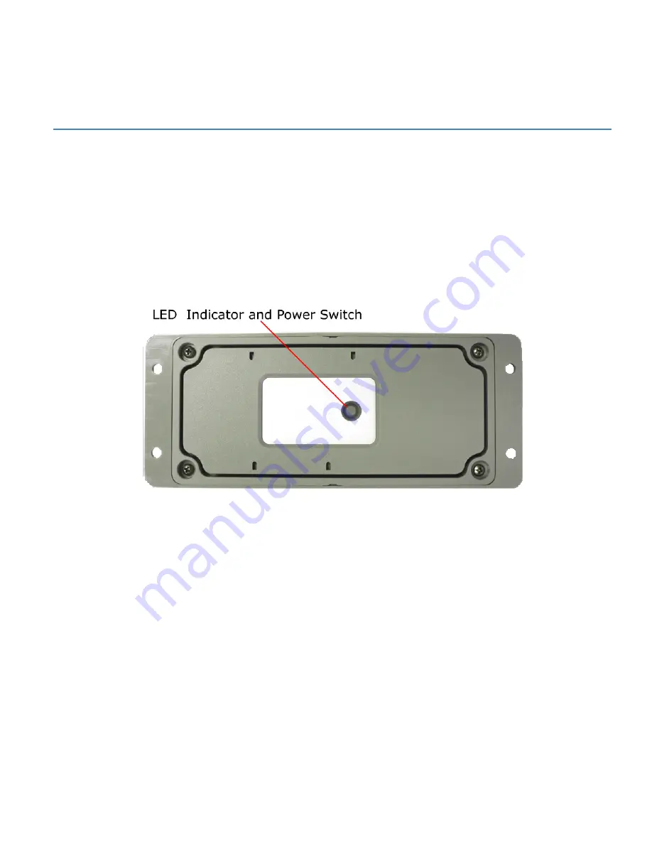
The button on the underside of the Spider AT 3000 functions as both the power switch and the activation
switch.

After the provisioning process is complete, the Spider AT 3000 will be activated. If you do not plan to
deploy the unit immediately, you should deactivate the Asset Tag, so as not to drain the battery.

To deactivate the Spider AT 3000, press and hold the power switch, located on the underside of the unit,
for three to five seconds. The LED will become solid red then go off. When the light is off, the unit is
deactivated.

Figure: 14  - LED Indicator and Power Switch

When you are ready to activate the Spider AT 3000, press and hold the power switch for three to five
seconds until you see a blinking light. The LED will then go off. When the light is off, the unit is activated.

- 32 -

Summary of Contents for Spider AT 3000

Page 1: ...AT 3000 Series User Guide GSM5218UG001 Version 1 00 01 March 2011 ...

Page 2: ...ve only a revocable and limited license to use such New Materials in connection with the products for which they are intended Distribution or modification of any New Materials without Enfora s consent is strictly prohibited IN NO EVENT WILL ENFORA BE RESPONSIBLE FOR ANY INCIDENTAL INDIRECT CONSEQUENTIAL OR SPECIAL DAMAGES AS A RESULT OF THE USE OF ANY NEW MATERIALS ENFORA S MAXIMUM LIABILITY FOR A...

Page 3: ...ot supplied by Enfora will continue to perform substantially in accordance with the product documentation This limited warranty is for the benefit of the original purchaser and is not transferable During the warranty period Enfora at its expense and in its sole discretion will repair the product or replace the product with a corresponding or equivalent product if it is determined to have a covered...

Page 4: ...caused by any accident misuse abuse improper installation handling or testing or unauthorized repair or modification of the product iii caused by use of any materials not supplied by Enfora or by use of the product other than in accordance with its documentation or iv the result of electrostatic discharge electrical surge fire flood or similar causes The purchaser or its customers as applicable sh...

Page 5: ...th the limits pursuant to Part 15 Subpart B Part 22 and Part 24 of the FCC rules These limits are designed to provide reasonable protection against harmful interference in an appropriate installation This equipment generates uses and can radiate radio frequency energy and if not used in accordance with instructions can cause harmful radiation to radio communication However there is no guarantee th...

Page 6: ... et 2 l utilisateur de l appareil doit accepter tout brouillage radioélectrique subi même si le brouillage est susceptible d en compromettre le fonctionnement L émetteur de la série Spider AT 3000 est configuré avec un facteur de devoir de transmission de 10 pour l opération de classe 8 GPRS Multislot au moins et est exclu de l évaluation de l exposition RF conformément aux exigences de RSS 102 ar...

Page 7: ... guidelines contained within this publication are guidelines and that each installation may have variables outside of the guidelines contained herein Said variables must be taken into consideration when installing or using the product and Enfora shall not be responsible for installations or transmissions that fall outside of the parameters set forth in this publication VI ...

Page 8: ... GPRS Compliance Specifications 11 2 1 Battery Specifications 12 2 1 Intrinsic Safety Specification 13 2 1 GPS Functionality 14 3 Initial Setup 15 3 1 Configure the Device 17 3 1 Configure the Spider AT 3000 series Manually using the Device Configuration Utility 18 3 1 Provision the Spider AT 3000 Series Using the Provisioner 19 4 Mounting the Unit 20 4 1 Hardware Needed To Mount the Device 21 4 1...

Page 9: ... and Down 32 7 Device Operation 33 7 1 Power Management 33 7 1 Position Reporting 34 7 1 Report Exceptions 35 7 1 Over the Air Configuration 36 7 Software Upgrade 37 7 1 Over the Air Upgrade 37 7 1 USB Upgrade 38 8 USB Driver Installation 39 8 1 Connect the Spider AT 3000 to a USB Port 39 8 2 Install the USB Drivers 39 9 SIM Card Installation 56 9 1 SIM Card Holder 56 9 2 SIM Card Installation 56 ...

Page 10: ...racket BRK5002 Top 26 Figure 12 Open Unit 30 Figure 13 Insert New Battery 31 Figure 14 LED Indicator and Power Switch 32 Figure 15 Found New Hardware Wizard Window 40 Figure 16 Hardware Wizard Install from specific location 41 Figure 17 Hardware Wizard Search for best driver 42 Figure 18 Hardware Wizard Install Progress 43 Figure 19 Hardware Wizard Completing 44 Figure 20 Hardware Wizard Install f...

Page 11: ...izard Install from List 52 Figure 28 Hardware Wizard Search for best driver 53 Figure 29 Hardware Wizard Windows Logo testing 54 Figure 30 Hardware Wizard Installation Complete 55 Figure 31 Spider AT 3000 SIM Holder 56 10 ...

Page 12: ...Table of Tables Table 1 Radio Performance Specifications 10 Table 2 GSM GPRS Compliance Specifications 11 Table 3 GPS Functionality 14 Table 4 Pilot Hole Diameter for Self Tapping Screws 28 11 ...

Page 13: ...e Spider AT 3000 series has the following features l Fully Integrated no need for external antenna or power source l Wireless Connection Reliability l Superior GPS Sensitivity Geofencing l Simplified Over the Air Configuration Provisioning The Spider AT 3000 series are based on Enfora s innovative Enabler III Low Power Platform with a built in programmable software environment Designed for the int...

Page 14: ...er AT 3000 series l CMS User Guide l Provisioner User Guide l Provisioner Quick Start Guide l Device Configuration Utility User Guide The following instructions and information relate to all Spider AT 3000 series products however for clarity only the Spider AT 3000 product will be referenced 2 ...

Page 15: ...00 series is a quad band integrated platform Inside the gray plastic case is an Enfora Enabler LPP0208 modem USB connector SIM holder and battery connector for the attached battery See 2 1 Overview Figure 1 Spider AT 3010 Circuit Board and Battery Pack 3 ...

Page 16: ...Figure 2 Top View of Spider AT 3000 Series Figure 3 Bottom View of Spider AT 3000 Series 4 ...

Page 17: ... then go off When the light is off the unit is deactivated When you are ready to activate the Spider AT 3000 press and hold the power switch for three to five seconds until you see a blinking light The LED will blink 12 times within a 3 second period if the battery voltage is in its highest range If the battery is within its normal voltage range the LED will blink on for one second off for one sec...

Page 18: ...l Width 69 mm l Height 21 mmSee Dimensions on page 6 l Weight with battery 207 grams l Weight without battery 150 grams The measurements of the Spider AT 3010 and 3011 are l Length 170 mm l Width 69 mm l Height 21 mm l Weight with battery 198 grams l Weight without battery 150 grams 6 ...

Page 19: ...Figure 4 Spider AT 3000 Dimensions 7 ...

Page 20: ...cation 2 2 Temperature Spider AT 3000 and Spider AT 3001 Compliant 20 C to 60 C Operating 30 C to 85 C Storage 40 C to 85 C Spider AT 3010 and Spider AT 3011 Compliant 20 C to 60 C Operating 40 C to 60 C Storage 40 C to 70 C 8 ...

Page 21: ...r Resistance The Spider AT 3000 series is an ingress resistant device pursuant to the IP 66 and IP 68 ratings This rating specifies that the device is fully protected against dust and can be immersed in water 9 ...

Page 22: ... 1 Radio Performance Specifications Frequency 850 900 1800 1900 MHz Sensitivity 108 dBm typical Transmit Power Class 4 2W 850 900 MHz Class 1 1W 1800 1900 MHz Table 1 Radio Performance Specifications 10 ...

Page 23: ...ifications The following list shows the certifications for the Spider AT 3000 FCC Parts 15 22 24 GCF Version 3 37 1 PTCRB Version 5 3 CE Mark Yes Industry Canada Yes RoHS Compliant Yes Table 2 GSM GPRS Compliance Specifications 11 ...

Page 24: ...LI SOCl2 Shelf Life 10 years 30 C Lithium Metal Content Approx 1 3 g Weight 60 g max Spider AT 3010 The Spider AT3010 uses a battery pack The features of this battery include l Greater energy density l Higher capacity l Extended lower temperature range l Allows for more rapid device reporting capability l Higher operating voltage l Long life l Patented safety features l Environmentally friendly Ba...

Page 25: ...U Directive 94 9 EC according to the standards EN 60079 0 2006 and EN 60079 15 2005 the product has been certified for Zone 2 Category 3 The Spider AT 3011 has been designed and tested to meet the following Intrinsic Safety Certifications Class I Division 1 groups C and D according to the requirements of UL913 and CSA 22 2 for use in the United States of America and in Canada The product is specif...

Page 26: ...pical Reacquisition 157 dBm typical Cold Start 147 dBm typical Position Accuracy horizontal 130 dBm Autonomous CEP 50 2m typical 150 dBm Autonomous CEP 50 2m typical 130 dBm Autonomous CEP 50 5m typical 150 dBm Autonomous CEP 50 5m typical Table 3 GPS Functionality 14 ...

Page 27: ...aging material 3 The Spider AT 3000 will be assembled loosely with four screws Fully loosen the screws and separate the two halves of the unit 4 Make sure the battery is connected See Connect the Battery on page 31 Figure 5 Internal View of Spider AT 3010 with Circuit Board and Battery Pack To Reduce the risk of ignition of a flammable or explosive atmosphere batteries must be inserted or changed ...

Page 28: ...owering Up and Down on page 32 9 Connect the USB cable to the circuit board and to your computer 10 Install the drivers See USB Driver Installation on page 39 11 Configure the Spider AT 3000 See Configure the Device on page 17 12 Once configuration is complete remove the USB connector and replace the battery pack 13 Close the Spider AT 3000 and replace the screws 14 The Spider AT 3000 is now activ...

Page 29: ...sing the Enfora Provisioner to configure the device over the air basic communication parameters must be configured using a terminal program and USB connection The only supported method of configuring the Spider AT 3000 with the basic parameters is to use the Device Configuration Utility The Spider AT 3000 requires Device Configuration Utility version 1 0 3 or later 17 ...

Page 30: ...n Utility you will be able to communicate with the server that is hosting the Provisioner software and configure the Spider AT 3000 over the air Refer to the Provisioner User s Guide for detailed device configuration instructions The default Spider AT 3000 parameters result in the device reporting to the server when activated and then once per day When not actively reporting to the server the devi...

Page 31: ...sing the Provisioner Once the device has been configured it will be ready to be provisioned by the Provisioner To provision the Spider AT 3000 over the air refer to the Provisioner User s Guide for detailed device configuration instructions 19 ...

Page 32: ...dhesive PSA Tape The optimal mounting position of the Spider AT 3000 is outdoors ensuring that the top of the device has clear access to the sky It is recommended that the user conducts testing in various situations in order to determine if the unit will Transmit data Acquire a GPS lock This procedure describes the mounting of the Spider AT Please read this entire procedure and ensure that all equ...

Page 33: ...er AT 3000 See 4 1 Hardware Needed To Mount the Device l Appropriate Mounting Screws Qty 4 l Appropriate Lock Washers Qty 4 l Appropriate Flat Washers Qty 4 l User defined hardware may also be used to mount the Device Mounting hardware is not included with the device Figure 6 Spider AT 3000 and Mounting Hardware 21 ...

Page 34: ...orientation provides optimum antenna performance l If the above mounting is not possible the unit may be mounted on its side where the label is mounted against the asset and the top of the unit faces towards the sky as much as possible l The selected mounting surface must not allow water to pool around the device l Care should be taken to avoid damaging wiring electronics plumbing etc when drillin...

Page 35: ...ing the proper location for the device hold the device in position Use the four screw hole openings to mark the center points for pre drilling Place the device aside and pre drill with the appropriate drill bit Figure 7 Spider AT 3000 Screw Hole 23 ...

Page 36: ...Insure the Device is activated See Powering Up and Down on page 32 Align the Device with the pre drilled screw holes Insert one of the screws assembled above through one of the screw holes in the Device Partially tighten the Screw into the mounting surface Repeat this process until all four screws are started into the mounting surface Now tighten the four screws until they are snug Tighten the Scr...

Page 37: ... Cable Ties The screw holes are sized so the Cable Ties can be inserted through them See 4 1 Alternate Mounting of the Device Figure 9 Mounting Cable Ties Take care not to fasten Cable Ties over sharp edges as this may cause excessive wear causing the Cable Ties to break 25 ...

Page 38: ...rs at 20g from 50 to 2000 Hertz In addition the release clasp has been tested to hundreds of cycles including temperature shock with near freezing liquid immersion Both the Spider AT 3000 series housing and BRK5002 bracket have been produced with UV stabilized plastic UV Stabilization prevents plastics from oxidizing and becoming brittle over time due to exposure to the sun Note For optimum perfor...

Page 39: ...C The minimum suggested application temperature is 50 F 10 C Note Initial tape application to surfaces at temperatures below the suggested minimum is not recommended because the adhesive becomes too firm to adhere readily However once properly applied low temperature holding is generally satisfactory To obtain good performance with all 3M VHB Tapes it is important to ensure that the surfaces are d...

Page 40: ...Pilot Hole Diameter for Self Tapping Screws Sheet Thickness mm Sheet Material From To Steel Aluminum 0 89 1 38 3 2 3 3 1 3 3 3 3 3 4 3 01 3 5 3 4 3 5 3 51 10 3 5 3 6 3 6 3 7 Table 4 Pilot Hole Diameter for Self Tapping Screws Attachment 1 Screw the bracket in place using the 4 provided self tapping screws 2 Firmly tighten the screws 3 Mount the device in the bracket 28 ...

Page 41: ...evice requires the battery to be changed use the following instructions Warning To Reduce the risk of ignition of a flammable or explosive atmosphere batteries must be inserted or changed only in a location known to be non hazardous 29 ...

Page 42: ...its mounted location 2 Fully loosen the four screws so the two halves of the unit are separated Figure 12 Open Unit 3 Disconnect the old battery by grasping the battery cable close to the connector and gently pull side ways 4 Remove the battery from the case 30 ...

Page 43: ... 5 1 Connect the Battery See Connect the Battery on page 31 Figure 13 Insert New Battery 2 Connect the new battery by attaching the connector to the battery terminals 3 Close the Spider AT 3000 and replace the screws Take care to Tighten the Screws to 2 5 in lb torque 4 Remount the device in its original location 31 ...

Page 44: ...g so as not to drain the battery To deactivate the Spider AT 3000 press and hold the power switch located on the underside of the unit for three to five seconds The LED will become solid red then go off When the light is off the unit is deactivated Figure 14 LED Indicator and Power Switch When you are ready to activate the Spider AT 3000 press and hold the power switch for three to five seconds un...

Page 45: ...lasts a few seconds while the motion sensor is measured to detect movement If no motion is detected then the device may return to the idle state If motion is detected then the GPS receiver is turned on l GPS receiver The microcontroller and GPS receiver are powered The GPS receiver acquires the GPS satellites and determines the current position A geofence may be used to determine if the new positi...

Page 46: ...roximate location The Spider AT 3000 will send a position report to the server immediately after being activated See Powering Up and Down on page 32 After activation the Spider AT 3000 can be configured to periodically report its position based upon several usage scenarios These usage scenarios include l Static Asset Monitoring with time interval reporting l Static Asset Monitoring with time of da...

Page 47: ...ssage will be sent at the next opportunity when the GSM modem is powered on to transmit the next scheduled position report A maximum of 10 messages will be stored l Time of day reporting without RTC The Spider AT 3000 uses valid GPS data to automatically set the RTC time If the Spider AT 3000 has not detected valid GPS data since the last activation then the RTC time will not be accurate If the Sp...

Page 48: ...s registered on the GSM network for a period of time and listens for new over the air configuration messages from the server Using the Provisioner the position reporting time or usage scenario may be modified The Spider AT 3000 can only receive new configuration commands when registered on the GSM network 36 ...

Page 49: ...grade 7 1 Over the Air Upgrade The Spider AT 3000 software may also be upgraded using the GSM network to program the device remotely over the air Refer to the Provision User Guide for details of the FOTA service 37 ...

Page 50: ...7 1 USB Upgrade A Windows application is available to upgrade the Spider AT 3000 software using the USB port See Initial Setup on page 15 for instructions to access the Spider AT 3000 USB port 38 ...

Page 51: ...a USB Port Supported Operating Systems include Windows 2000 Windows XP and Windows Vista When you connect the Spider AT 3000 to the computer you will be prompted to install the drivers Note In order to access the USB port on the Spider AT 3000 you will need to remove the cover The USB connector is located on the circuit board inside the unit Follow the steps in the next section to install the driv...

Page 52: ...omatically begin again The second step will install the Enabler III LPP Trace The third step will install the Enabler III LPP Modem 1 The Windows Operating System will detect the new USB device 2 You will see the following screen Figure 15 Found New Hardware Wizard Window 3 Click on No not this time 4 Click Next 5 You will see the following screen 40 ...

Page 53: ...Figure 16 Hardware Wizard Install from specific location 6 Click the radio button next to Install from a list or specific location Advanced 7 Click Next 8 You will see the following screen 41 ...

Page 54: ... best driver 9 Click on the check box marked Include this location in the search 10 Browse to the location on your computer where the USB drivers are located 11 Click Next 12 You will see the screen that shows the installation progress 42 ...

Page 55: ...Figure 18 Hardware Wizard Install Progress 13 When the installation of the Locosto USB device is complete you will see the following screen 43 ...

Page 56: ...Figure 19 Hardware Wizard Completing 14 Click Finish When this installation is complete the installation process for the USB device will begin You will see the following screen 44 ...

Page 57: ...Figure 20 Hardware Wizard Install from specific location 15 Click on No not this time 16 Click Next 17 You will see the following screen 45 ...

Page 58: ...Figure 21 Hardware Wizard Install from List 18 Click the radio button next to Install from a list or specific location Advanced 19 Click Next 20 You will see the following screen 46 ...

Page 59: ...rd Search for best driver 21 Click on the check box marked Include this location in the search 22 Browse to the location on your computer where the USB drivers are located 23 Click Next 24 You may see the following screen 47 ...

Page 60: ...Figure 23 Hardware Wizard Windows Logo testing Note If you see this warning click on Continue Anyway 25 You will see the screen that shows the installation progress 48 ...

Page 61: ...Figure 24 Hardware Wizard Installation Progress 26 When the installation of the Enfora Enabler III LPP Trace is complete you will see the following screen 49 ...

Page 62: ...Figure 25 Hardware Wizard Installation Complete 27 Click Finish When this installation is complete the installation process for the USB device will begin You will see the following screen 50 ...

Page 63: ...Figure 26 Hardware Wizard New Hardware 28 Click on No not this time 29 Click Next 30 You will see the following screen 51 ...

Page 64: ...Figure 27 Hardware Wizard Install from List 31 Click the radio button next to Install from a list or specific location Advanced 32 Click Next 33 You will see the following screen 52 ...

Page 65: ...rd Search for best driver 34 Click on the check box marked Include this location in the search 35 Browse to the location on your computer where the USB drivers are located 36 Click Next 37 You may see the following screen 53 ...

Page 66: ...Figure 29 Hardware Wizard Windows Logo testing Note If you see this warning click on Continue Anyway 54 ...

Page 67: ...Figure 30 Hardware Wizard Installation Complete 38 Click Finish to complete the installation of the Enfora Enabler III LPP Modem drivers 55 ...

Page 68: ...000 SIM Holder 9 2 SIM Card Installation 1 Slide the SIM card into the open SIM holder 2 Make sure the SIM card notch is lined up properly See 9 SIM Card Installation 3 Close the holder and slide it until it is completely closed Note The SIM card is not provided with the Spider AT 3000 device The SIM must be obtained from the GSM GPRS service provider and must be provisioned by the operator for da...

Page 69: ... 57 ...

Reviews: