background image

27

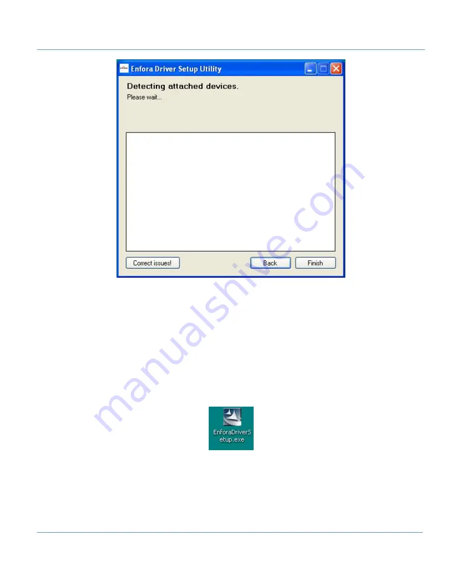
Figure: 22  - Enfora Driver Setup Utility Attached Devices Window

4.2 USB Driver Installation Using The Enfora Driver Setup
Utility (Windows 7)

These instructions illustrate how to correctly install the USB drivers in Windows 7 using the Enfora Driver
Setup Utility.

1. Run the Enfora Driver Setup Utility by double-clicking the

EnforaDriverSetup

executable file.

The Enfora Driver Setup Utility Welcome window opens.

Summary of Contents for MT 3050

Page 1: ...MT 3050 User Guide EMT3050UG001 Version 1 00 22 January 2013 ...

Page 2: ...representation with respect to the merchantability suitability functionality accuracy or completeness of any such New Materials The user of such New Materials assumes all risk known or unknown of such use Enfora reserves all rights in such New Materials The user shall have only a revocable and limited license to use such New Materials in connection with the products for which they are intended Dis...

Page 3: ...introduced into a retrieval system or transmitted in any form or by any means electronic mechanical photocopying recording or otherwise or for any purpose without the express written permission of Enfora Inc Enfora and the Enfora logo are either registered trademarks or trademarks of Enfora Inc in the United States 251 Renner Pkwy Richardson TX 75080 USA Phone 972 633 4400 Fax 972 633 4444 Email i...

Page 4: ...re not supplied by Enfora will continue to perform substantially in accordance with the product documentation This limited warranty is for the benefit of the original purchaser and is not transferable During the warranty period Enfora at its expense and in its sole discretion will repair the product or replace the product with a corresponding or equivalent product if it is determined to have a cov...

Page 5: ... ii caused by any accident misuse abuse improper installation handling or testing or unauthorized repair or modification of the product iii caused by use of any materials not supplied by Enfora or by use of the product other than in accordance with its documentation or iv the result of electrostatic discharge electrical surge fire flood or similar causes The purchaser or its customers as applicabl...

Page 6: ...sted and found to comply with the limits pursuant to Part 15 Subpart B Part 22 and Part 24 of the FCC rules These limits are designed to provide reasonable protection against harmful interference in an appropriate installation This equipment generates uses and can radiate radio frequency energy and if not used in accordance with instructions can cause harmful radiation to radio communication Howev...

Page 7: ...nada This device complies with Industry Canada licence exempt RSS standard s Operation is subject to the following two conditions 1 this device may not cause interference and 2 this device must accept any interference including interference that may cause undesired operation of the device The MT 3050 transmitter is configured with a 10 transmission duty factor for GPRS Multislot class 2 operation ...

Page 8: ... law code or regulation including local or state codes performed by a third party Enfora strongly recommends that all installations hookups transmissions etc be performed by persons who are experienced in the fields of radio frequency technologies Enfora acknowledges that the installation setup and transmission guidelines contained within this publication are guidelines and that each installation ...

Page 9: ...porting 8 2 7 1 Vehicle Identification Number VIN 8 2 7 2 Excessive Engine Speed RPM 8 2 7 3 Vehicle Speed 9 2 7 4 Vehicle Battery Voltage Low Battery Warning 9 2 7 5 Check Engine Light MIL Alert 9 2 7 6 Trip Odometer Reporting 9 2 7 7 Idle Time Reporting 10 2 7 8 Low Fuel Alert 10 2 7 9 Rapid Acceleration 10 2 7 10 Sudden Deceleration Harsh Braking 11 2 7 11 Motion Detection 11 2 7 12 OBDII Basic...

Page 10: ...ce 15 3 1 2 Inserting The SIM 17 3 1 3 Closing The Device 17 3 2 Activating The Device 18 3 3 Device Installation 18 3 4 Accelerometer Calibration 19 4 USB Driver Installation 21 4 1 USB Driver Installation Using The Enfora Driver Setup Utility Windows XP 21 4 2 USB Driver Installation Using The Enfora Driver Setup Utility Windows 7 27 5 Network Test Procedure 35 5 1 Configuring The Modem For Test...

Page 11: ... it includes a disconnect alert feature using an in device backup battery It is available in GSM GPRS 1xRTT and HSDPA versions The MT 3050 contains an internal GPS a cellular antenna a J1962 compliant OBDII connector a micro USB connector and 3 LED indicators The GSM2378 and UMT2212 variants also contain an internal SIM card holder Figure 1 Front Right View Figure 2 Front View ...

Page 12: ...2 The MT 3050 has a printed label on the top side of the device The figure below shows the information included on the label Figure 3 MT 3050 Labels ...

Page 13: ... l CDMA SMS Text MO MT OBD Protocols l ISO 15765 CAN l ISO 9141 2 l ISO 14230 KWP 2000 l J1850 PWM l J1850 VPW Some vehicles only support a subset of these protocols which may limit the functionality of the MT 3050 SIM Card Interface I O l SIM Access Internal l Cellular Antenna Internal l GPS Antenna Internal l LEDs GPS blue Cellular green OBD red l I O Connector Micro USB 2 0 command port l OBDII...

Page 14: ...nt l SMS Indication l GPS Distance Certifications l FCC Yes l CE Yes l RoHS Compliant Yes l Industry Canada Yes Document References l Spider MT 3050 AT Command Set For GPRS EMT3050AT001 l Spider MT 3050 AT Command Set For 1xCDMA EMT3050AT002 l Spider MT 3050 AT Command Set For HSDPA EMT3050AT003 l GSM Network Configuration Worksheet GSM0000AN019 Applicable Products The MT 3050 series has three mod...

Page 15: ...e RPM l GPS information l Idle time l Low fuel l Trip Odometer trip distance l Vehicle battery voltage low battery warning l Vehicle Identification Number VIN l Vehicle speed l Other events monitored by the OBDII system Some vehicles are not compatible with the MT 3050 If the vehicle is not compatible with the parameters the MT 3050 requires then functionality may be limited problematic or unavail...

Page 16: ... data points l Enfora Binary Packets l Buffered GPS message feature l Geo fencing l Virtual odometer 2 2 LEDs The MT 3050 includes LEDs to indicate OBDII NETWORK and GPS status The following figures show the MT 3050 connectors and LEDs Figure 4 MT 3050 Connectors Figure 5 MT 3050 LEDs ...

Page 17: ... requires 9 16 VDC minimum 2 amps input power Pin 16 on the 16 Pin IO connector is the positive power input and pin 4 and 5 is the ground This device contains a battery This battery is not to be removed or replaced by the user Please dispose of this device according to local recycling laws 2 4 Accelerometer The three axis digital accelerometer provides the following features l Motion alert towing ...

Page 18: ... list of data returned therefore not all vehicles support retuning the Vehicle Identification Number 2 7 2 Excessive Engine Speed RPM Excessive engine speed alerts are triggered when the engine speed in RPM exceeds a defined RPM level in RPM increments for a defined period of time in seconds e g 30 seconds The MT 3050 has three definable thresholds Unnecessary wear and tear on the powertrain contr...

Page 19: ...age alert is triggered when the vehicle s battery is reported to be below a threshold e g 10 8 V for a user defined period of time in seconds e g 300 seconds The following AT Command example sets the low battery threshold to 10 8 volts When the voltage remains below this threshold for 300 seconds 5 minutes it triggers an input event Restoring voltage above the threshold for 300 seconds 5 minutes w...

Page 20: ... low fuel alert triggers when the vehicle s fuel level falls below a defined threshold in percent e g 12 for a defined period of time in seconds e g 60 seconds The following AT Command example sets the low fuel alert threshold to 12 for 1 minute 60 seconds with a clearance time of 30 seconds If the fuel level remains below this threshold for 60 seconds it triggers the input event Restoring the fue...

Page 21: ...movement via the accelerometer occurs when the vehicle ignition is off and the vehicle is stationary A motion alert is triggered when motion defined in milli Gs is detected for a defined period of time 2 7 12 OBDII Basic Event Data Five additional data items can be included with event messages l VIN l Firmware version PKG l OBD Protocol i e J1850 PWM l Cellular signal strength RSSI l OBD speed 2 7...

Page 22: ...lerometer in milli Gs e g 0 75 for a defined period of time in seconds e g 30 seconds The following AT command example sets the Up accelerometer threshold to 1 2Gs If this threshold is exceeded for 1 second trigger the input event This event will clear in 30 seconds when the acceleration is below this threshold AT OBDAUP 1 1200 1 30 2 7 16 Down Down accelerometer events can be triggered when the t...

Page 23: ...her USB devices and nothing should be connected to this port when the vehicle is in motion The MT 3050 can not be powered through the USB Port The micro USB connector is only used to program the modem When programming the modem a micro USB cable is required which you must purchase separately Figure 7 Micro USB Cable 2 9 Additional Software Features 2 9 1 AT Commands Over SMS A user can send AT com...

Page 24: ...read messages drops down to 49 after successful transmission of that message However if a user sends AT GPSLOGRD 0 1 99 then the total number of unread messages still remains at 50 that message is transmitted to the remote server A user can also read a message stored in the memory by inputting the appropriate starting index number 2 9 3 Synchronize RTC Time With GPS Time The Real Time Clock RTC is...

Page 25: ...no external access to the SIM The RTT221 CDMA version of the MT 3050 does not use a SIM and should not be opened 3 1 1 Opening The Device To prevent damaging the device we highly recommend that you use the Plastic Lever Enfora part number ASA 3000 0001 when opening the MT 3050 To open the MT 3050 follow these steps 1 Insert the tool into the opening and gently push until that corner of the lid uns...

Page 26: ...g the MT 3050 Case 2 Repeat step 1 for the other corner Figure 9 MT 3050 With Cover Unsnapped 3 Carefully slide the cover off the device Figure 10 MT 3050 With Cover Partially Removed Figure 11 MT 3050 With Cover Removed ...

Page 27: ...g the correct tool carefully remove the device cover to access the internal SIM holder as pre viously described 2 Insert the SIM into the SIM holder of the MT 3050 3 Replace the cover as described in the next section 3 1 3 Closing The Device Replace the MT 3050 cover by using the following steps A Place the MT 3050 cover onto the base as shown in the following figure 1 Apply gentle downward pressu...

Page 28: ... provided to the provider To verify that the activation has successfully completed attempt a voice call AT CDVxxxxxx If the call is successful then the OTASP Over the Air Service Provisioning was successful 3 3 Device Installation Make sure the vehicle is parked on level ground prior to installing the MT 3050 Instructions provided in this section describe the hardware installation of the MT 3050 d...

Page 29: ...talled and the vehicle s ignition is turned on 3 4 Accelerometer Calibration The accelerometer undergoes an automatic calibration sequence on the first drive after any of the following events l Device installation l Software upgrade l Vehicle battery replacement or recharge if battery was fully discharged l Device auxiliary processor reset ...

Page 30: ...ure the vehicle is parked on level ground prior to installing the MT 3050 2 Drive the vehicle in a straight path on level ground during the automatic calibration An inclined sur face will put part of the gravity vector into the XY plane which will affect the acceleration thresh olds A 5 7 degree angle will place 10 of the gravity vector into the XY plane When the vehicle passes 32 KPH the auxiliar...

Page 31: ...nstructions illustrate how to correctly install the USB drivers in Windows XP using the Enfora Driver Setup Utility 1 Run the Enfora Driver Setup Utility by double clicking the EnforaDriverSetup executable file The Enfora Driver Setup Utility Extraction window opens Figure 14 Enfora Driver Setup Utility Extraction ...

Page 32: ... Once the contents have been extracted to memory the Welcome Window opens Figure 15 Enfora Driver Setup Utility Welcome 2 To install the drivers select Install The Enfora Driver Setup Utility Window opens ...

Page 33: ...ow opens while the system installs the drivers 4 Disconnect any Enfora devices Previous drivers will be removed during this phase During the installation your computer s display may freeze and appear non responsive If this occurs allow the computer to continue working After 2 3 minutes the display and installer will resume normal behavior ...

Page 34: ...24 Figure 17 Enfora Driver Setup Utility Installation Window Figure 18 Enfora Driver Setup Utility Driver Installation 5 When prompted to install the device driver select Next ...

Page 35: ...25 Figure 19 Enfora Driver Setup Utility Driver Installation Progress You may see the following warning message Figure 20 Windows Security Window ...

Page 36: ...he USB drivers is complete the Completion window opens Figure 21 Enfora Driver Setup Utility Driver Install Completion Window 7 Click Finish When the installation is complete the list of attached devices will appear within the Attached Devices Window ...

Page 37: ...nfora Driver Setup Utility Windows 7 These instructions illustrate how to correctly install the USB drivers in Windows 7 using the Enfora Driver Setup Utility 1 Run the Enfora Driver Setup Utility by double clicking the EnforaDriverSetup executable file The Enfora Driver Setup Utility Welcome window opens ...

Page 38: ...28 Figure 23 Enfora Driver Setup Utility Welcome Window Once the contents have been extracted to memory the Driver Setup Window opens ...

Page 39: ...29 Figure 24 Enfora Driver Setup Utility Preparation Window 2 To install the drivers click Install The Enfora Driver Setup Utility Prepare System Window opens ...

Page 40: ...w opens while the system installs the drivers 4 Disconnect any Enfora devices Previous drivers will be removed during this phase During the installation your computer s display may freeze and appear non responsive If this occurs allow the computer to continue working After 2 3 minutes the display and installer will resume normal behavior ...

Page 41: ...31 Figure 26 Enfora Driver Setup Utility Driver Installation 5 When prompted to install the device driver select Next Figure 27 Windows Security Window 6 Select Install this driver software anyway ...

Page 42: ...l compatibility issues Figure 28 Enfora Driver Setup Utility Driver Install Completion Window When installation of the USB drivers is complete the Completion window opens 7 If there are no errors click Finish 8 If the status displays an issue click Correct issues 9 At the OK to apply fix prompt click Yes ...

Page 43: ... Setup Utility Attached Devices Window Figure 30 Enfora Driver Setup Utility Apply Fix Window When the installation is complete the list of Attached Devices appears within the Enfora Driver Setup Utility Attached Devices window ...

Page 44: ...34 Figure 31 Enfora Driver Setup Utility Attached Devices Window ...

Page 45: ...es are addressed in the following configuration commands l Modem ID name My_MT_TEST l Remote Server address http apitest enfora com UDPAPP l Remote Server IP port 1721 Give the modem a unique name with the following command AT MDMID My_MT_TEST This command combined with the wakeup message will allow the server to associate a Public IP address with a specific modem and can create an opportunity whe...

Page 46: ...on your computer To install Java Runtime please visit the Java website here http www java com en download manual jsp 1 Start a web browser and enter the following URL http apitest enfora com UDPAPP Figure 32 apitest enfora com UDPAPP Window 2 Enter the name used in the Modem ID MDMID command in the box 3 Select Connect ...

Page 47: ...age in the window Selecting the Clear button will erase the contents from the ASCII Data window 5 Enter the following command in the Command Data text box ATI 6 Click on the Submit button 7 Verify that you see the modem response Enfora Inc If so you have successfully configured the modem to talk with the server ...

Page 48: ... known position can be configured to be used in the output message AT OBDBBT is used to configure the time in seconds that the device will stay powered after removal from the vehicle The range is 30 6000 with the default being 600 In addition to prevent damage to the battery the device will turn itself off when the battery reaches the level determined to be the lowest safe value If the configured ...

Reviews: