background image

PROFInet Module   


SINUS H 


31

/

34 

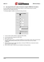
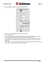
The following diagram explains the parameter reading procedure.   


Inverter communication address is assigned to PNU [1000]. 

PNU [1003] is set to 0. 

When PNU [1002] is set to 2, the Sinus H PROFInet communication module references PNU 
[1000] and reads the data saved in the inverter’s internal address pointed by it. 

After reading the inverter’s internal parameters, the Sinus H PROFInet communication module 
saves the result to PNU [1003]. If the reading procedure is successful, it saves the read data to 
PNU[1001]. 

PNU [1003] is used to verify successful completion of reading procedure. If the reading procedure 
is successful, the PLC reads the data saved at PNU[1001]. 


Sinus H Parameter Reading 

Summary of Contents for SINUS H PROFInet

Page 1: ...cture or operating cycle of the product must be performed or authorized by Enertronica Santerno S p A Enertronica Santerno S p A assumes no responsibility for the consequences resulting by the use of non original spare parts Enertronica Santerno S p A reserves the right to make any technical changes to this manual and to the product without prior notice If printing errors or similar are detected t...

Page 2: ... instructions carefully Particular attention should be paid because danger of an electric shock may be present Keep operating instructions handy for quick reference Read the operating instructions carefully to fully understand the functions of the Sinus H series and to use it properly CAUTION Be cautious when handling the CMOS components of the communication module Static may lead to malfunctionin...

Page 3: ...elated Keypad Parameters 11 5 Keypad Parameters Related to PROFInet Communication Module 13 5 1 CNF Group 13 5 2 DRV Group 13 5 3 COM Group 14 5 4 PRT Group 17 6 PROFIdrive Status Diagram 18 7 Supported PROFIdrive Cyclic Telegram 20 7 1 Standard Telegram Mode 0 20 7 2 Vendor Specific Telegram Mode 1 20 8 Supported PROFIdrive Parameters 25 9 Fault Message Counter PNU 944 and Fault Number PNU 947 27...

Page 4: ...ation and easier maintenance 1 1 PROFInet Technical Features Item Description Communication protocol PROFInet IO CC A Communication speed 100 Mbps Communication type Full Duplex Distance 100m Twisted Pair Max number of Node 64 each Service PROFIdrive Class 1 Topology Line Tree Star topology 1 2 Included Items This product P N ZZ0176104 is consisting of these kinds of parts PROFInet Communication M...

Page 5: ...unication module is removed or installed the power supply should be switched off Otherwise the Sinus H inverter will be damaged entirely Take off PROFInet communication module from the product after the power supply is totally discharged Unfasten the front cover fixing bolt to remove the front cover and remove I O cover 1 2 from a dedicated Sinus H inverter for communication ...

Page 6: ... PROFInet Module 6 34 Remove the keypad 3 Unfasten a screw from I O board and fasten the prepared brass bar 4 and 5 Mount PROFInet communication Module 6 and fasten the removed screw 7 and the included screw 7 ...

Page 7: ...PROFInet Module SINUS H 7 34 Install the keypad 9 at first and the communication module cover 10 in order Install the front cover 11 again And installation is completed ...

Page 8: ...F LINK2 is not connected to a network Yellow Normal operation OFF Network LINK1 is not transmitting receiving data Flashing Data transmission between the master unit and the communication module is in progress at network LINK2 LED2 ERROR Red Normal operation OFF Communication between the communication module and the inverter is normal Communication fault CPU and ERROR indicators flash simultaneous...

Page 9: ...34 Indicator Color Description Status Remarks boot up LED3 CPU Green Abnormal operation ON The CPU is not operating OFF Normal operation Flashing 1 second intervals The communication module is installed correctly in the inverter ...

Page 10: ...White Green 4 NONE Not Used Blue 5 NONE Not Used White Blue 6 RX Data Reception Green 7 NONE Not Used White Brown 8 NONE Not Used Brown 3 2 Communication Cable Connector Wires connected to pin 1 and pin 2 must be twisted Wires connected to pin 3 and pin 6 must be twisted 3 3 Network Cable Specification PROFInet network communication requires STP category 6a or higher network cables 1 8 1 2 3 4 5 6...

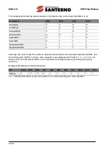
Page 11: ...t Description CNF 30 Option 1 Type When the Sinus H PROFInet communication module is installed the module type PROFInet is automatically detected and displayed Note 1 DRV 06 Cmd Source 1 Fx Rx 1 0 Keypad 1 Fx Rx 1 2 Fx Rx 2 3 Int 485 4 Fieldbus 5 UserSeqLink 07 Freq Ref Src 0 Keypad 1 0 Keypad 1 1 Keypad 2 2 V1 4 V2 5 I2 6 Int 485 8 FieldBus 9 UserSeqLink 12 Pulse COM 06 FBus S W Ver 09 FBus Led 1...

Page 12: ...ay 1 19 opt para 10 0 Gateway 2 20 opt para 11 0 Gateway 3 21 opt para 12 0 Gateway 4 22 opt para 13 0 Mode 0 STD Telegram1 1 Vendor Specific Telegram PRT 12 Lost Cmd Source 0 None 0 None 1 Free Run 2 Dec 3 Hold Input 4 Hold Output 5 Lost Preset 13 Lost Cmd Time 1 0 0 1 120 s 14 Lost Preset F 0 00 0 50 60 00 Hz ...

Page 13: ... PROFInet communication module is installed in the Sinus H inverter 5 2 DRV Group 5 2 1 DRV 06 Cmd Source Command Source Selection Selects the command source for the Sinus H inverter Set the parameter to 4 FieldBus to set PROFInet communication as the command source 5 2 2 DRV 07 Freq Ref Src Frequency Reference Source Selection Selects the frequency reference source for the Sinus H inverter Set th...

Page 14: ...stalled communication module 5 3 2 COM 09 FBus LED Communication Module Status Indicator LED Information Displays the communication module s status indicator LED information on the inverter s keypad For more information refer to 2 Part Names and Installation An example of COM 09 FBus LED status displayed on the keypad Indicator Name LINK1 ACT1 LINK2 ACT2 ERR CPU Status OFF ON ON ON ...

Page 15: ...nding a DCP packet For example when programming a PLC in Siemens TIA you can select Set IP address in the project to allow the PLC to send a DCP packet to a communication module to set an IP address If you select IP address is set directly at the device the PLC reads the IP address set at the communication module and uses it for PROFInet network communication instead of resetting the IP 5 3 4 COM ...

Page 16: ...drive Cyclic Telegram for the supported telegram types and the details Setting Selected Telegram Type 0 Standard Telegram 1 Vendor Specific Telegram 5 3 5 COM 94 Comm Update Press Yes to reflect the values setup with keypad on the PROFInet option ...

Page 17: ...reference received before the command loss 4 Hold Output The inverter keeps operating using the operation frequency it was operating at before the command loss 5 Lost Preset The inverter operates using the frequency reference set at Pr 14 Lost Preset F 5 4 2 PRT 13 Lost Cmd Time Lost Command Decision Time Sets the time taken for the inverter to decide that a command has been lost and apply the Los...

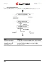
Page 18: ...munication module uses Status Description S1 Switching On Inhibited The communication module cannot be switched ON at the moment S2 Ready For Switching On The communication module can be switched ON at any moment S3 Ready For Operation Communication module operation is ready to be enabled S4 Operation enable The motor is running ...

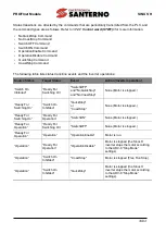
Page 19: ...d Ready For Switching On SwitchOFF and NoQuickStop and NoCoastStop None Motor is stopped Ready For Switching On Switch On Inhibited QuickStop or CoastStop None Motor is stopped Ready For Switching On Ready For Operation SwitchON None Motor is stopped Ready For Operation Ready For Switching On SwitchOFF None Motor is stopped Ready For Operation Operation OperationEnable Motor is run Operation Ready...

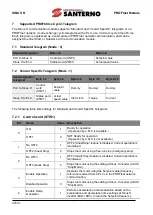
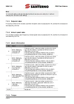
Page 20: ...Torque Current The following table lists settings for Standard and Vendor Specific Telegrams 7 2 1 Control word STW1 Bit Name Value Description 0 ON 1 Ready for operation Operation by a PLC is available OFF1 0 NOT Ready for operation Operation by a PLC is not available 1 No OFF2 1 OFF2 Coast Stop feature is disabled Current operation is maintained OFF2 Coast Stop 0 Stops the motor using a free run...

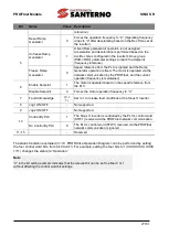
Page 21: ... Setpoint 1 The motor is operated based on the speed reference from the PLC Disable Setpoint 0 Forces the motor operation frequency to 0 7 Fault Acknowledge 0 1 Set to 1 to release fault conditions at the Sinus H inverter 8 Jog1 ON OFF Not supported 9 Jog2 ON OFF Not supported 10 Control By PLC 1 The Sinus H inverter is controlled by the PLC s control word STW1 received via the PROFInet network co...

Page 22: ...ternally the control uses the inverter s operation command at communication address 0x0382 and the Control word STW1 for basic motor operation uses address 0x47F bits 0 1 2 3 4 5 6 10 When a PLC sets the bits at 0x47F motor operation is possible simply by providing a frequency reference Example Bit Settings for Motor Operation Bit Bit10 Bit9 Bit8 Bit7 Bit6 Bit5 Bit4 Bit3 Bit2 Bit1 Bit0 Setting 1 N...

Page 23: ...ntrol is not available 0 Switching On Not inhibited Control is available 7 Warning Present 1 Warning condition is present at the inverter No Warning Present 0 Warning condition is not present at the inverter 8 Speed Error within tolerance 1 The motor speed has reached the frequency reference Setpoint value Speed Error out of tolerance 0 The motor speed has not reached the frequency reference Setpo...

Page 24: ...an one bit in the latch type trip information 2 parameter bit field is set to 1 Otherwise it is set to 0 This bit references address 0h0331 in the inverter s compatible parameter communication addresses 2 Bit for displaying level type trip information This bit is set to 1 when more than one bit in the level type trip information parameter bit field is set to 1 Otherwise it is set to 0 This bit ref...

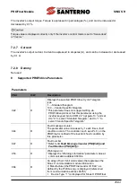
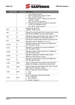
Page 25: ...is parameter using the inverter keypad Go to COM 22 opt para 13 and set it to 0 to select Standard Telegram and to 1 to select Vendor Specific Telegram 944 R Fault message counter The parameter value increases by 1 each time a fault condition occurs The controller such as a PLC on the PROFInet is notified of the inverter s fault condition by this parameter 947 R Fault number Refer to 9 Fault Messa...

Page 26: ...ion module is reset when the parameter value is changed to 1 from 0 61000 R Displays the device name of the Sinus H PROFInet communication module 61001 R Displays the IP address of the Sinus H PROFInet communication module 61002 R Displays the MAC address of the Sinus H PROFInet communication module 61003 R Displays the gateway IP address of the Sinus H PROFInet communication module 61004 R Displa...

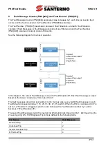
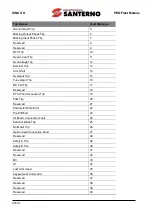
Page 27: ...he current Fault Message is saved at Fault Situation 1 Each fault message is saved based on the time of occurrence from index 0 to 63 The fault messages are written overwritten to the memory when every eighth fault message in each Fault Situation is saved at index 7 15 23 31 39 47 55 and 63 When the PLC s control word bit 7 is set to 1 a Fault Ack is triggered which in turn increases the Fault Sit...

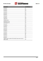
Page 28: ...rt 14 Overheat Trip 15 Fuse Open Trip 16 MC Fail Trip 17 Reserved 18 PTC Thermal sensor Trip 19 FAN Trip 20 Reserved 21 Parameter Write Error 22 Pre PID Fail 23 IO Board Connection Fault 24 External Brake Trip 25 No Motor Trip 26 Option Card Connection Fault 27 Reserved 28 Safety A Trip 29 Safety B Trip 30 Reserved 31 Reserved 32 BX 33 LV 34 Lost Command 35 Keypad Lost Command 36 Reserved 37 Reser...

Page 29: ...45 Reserved 46 Reserved 47 Reserved 48 ADC Error 49 EEPROM Error 50 Watchdog 1 Error 51 Watchdog 2 Error 52 Reserved 53 QueueFull 54 Reserved 55 Reserved 56 Reserved 57 Reserved 58 Reserved 59 Reserved 60 Reserved 61 Reserved 62 Reserved 63 Internal Communication Error between the Inverter and the Option Card 64 ...

Page 30: ...ion address is assigned to PNU 1000 2 Inverter setting data is assigned to PNU 1001 3 PNU 1003 is set to 0 4 When PNU 1002 is set to 1 the Sinus H PROFInet communication module references the values assigned at PNU 1000 and PNU 1001 and writes the values to the inverter s internal parameters 5 After writing the inverter s internal parameters the Sinus H PROFInet communication module saves the resu...

Page 31: ...PNU 1000 and reads the data saved in the inverter s internal address pointed by it 4 After reading the inverter s internal parameters the Sinus H PROFInet communication module saves the result to PNU 1003 If the reading procedure is successful it saves the read data to PNU 1001 5 PNU 1003 is used to verify successful completion of reading procedure If the reading procedure is successful the PLC re...

Page 32: ...the PROFInet Record Data from the index address 0h5000 Using the PROFInet IO RW service you can directly access the addresses to perform reading and writing For example Siemens PLC users may access the inverter s parameter data mapped to the PROFInet Record using WRREC and RDREC function blocks Refer to the user s manual that that is supplied with the inverter for more information about the invert...

Page 33: ...lot Number Alarm Specifier User Structure Identifier Channel Properties Channel Error Type Fault Occurrence 0h3A00 1 2 Diagnosis 0h8000 0h0800 9012 Fault Release 0h3A00 1 2 Diagnosis 0h8000 0h1000 9012 After a fault alarm is received the PLC has to read the inverter trip parameters to collect detailed information about the fault trip such as the fault trip type latch type trip 1 latch type trip 2 ...

Page 34: ...tomer Service 4 CPU indicator is flashing in 1 second intervals and ERROR indicator is flashing in 2 second intervals Check the communication link where the LAN cable is connected and ensure that the LINK indicator is turned on If the LINK indicator is turned off check the LAN cable and ensure that it is properly connected to the link port Check to ensure that the communication module s device nam...

Reviews: