


16
10.0 MAINTENANCE
10.1 Preparation for Maintenance
All cutter maintenance procedures must be performed
under the following conditions:
• Material must be removed from the cutting head.
• The battery must be removed from the cutter.
• The cutter must be given time to cool to prevent burns.
• Procedures must be performed in a suitable work
environment in accordance with all current safety
regulations and/or laws in your country or region.
• The cutter must be cleaned thoroughly before
maintenance procedures are performed.
• Suitable personal protective equipment (PPE) must be
used and/or worn while performing any work.
NOTICE:
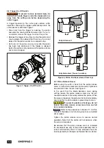
WARNING
The cutter must sometimes be
operated in order to complete a maintenance or
repair procedure being performed, or to prepare it
for a procedure that is about to be performed.
However, to prevent startup while persons are
working on the cutter, always remove the battery
from the cutter before beginning any procedure
steps that require use of tools and/or physical
contact with the cutter. Failure to observe this
precaution may result in death or serious personal
injury.
NOTICE:
WARNING
Ensure that cutter blade safety guard
has been correctly reinstalled before placing the
cutter back into service after maintenance
procedures are completed. Failure to reinstall this
guard could result in serious personal injury.
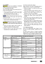
10.2 Periodic Maintenance Chart
Refer to the Periodic Maintenance Chart (Table 1) for a
list of various routine checks and procedures.
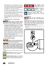
10.3 Cleaning
• Clean the cutter using a dry cloth or compressed air.
For plastic surfaces, use a cloth slightly dampened
with water.
NOTICE:
CAUTION
To prevent possible injury, always wear
safety glasses or face mask when using compressed
air.
• Be sure there are no traces of oil, grease or corrosive
substances on the tool, especially on the grips.
• Use a damp cloth and soapy water to clean plastic
components.
• Do not use gasoline or thinner to clean the tool.
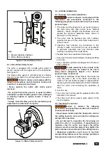
10.4 Fasteners
Periodically check all screws, nuts and other fasteners
for proper tightness. Tighten any loose fasteners.
Replace any worn or damaged fasteners. This should
be performed periodically or every day in the event of
frequent or prolonged cutter operation.
NOTICE
Failure to check and tighten fasteners as
required may result in serious damage to the cutter.
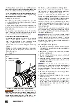
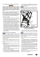
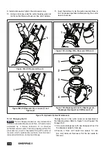
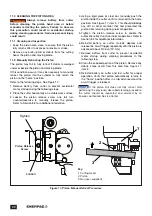
10.5 Cutter Hydraulic System
The cutter contains a small hydraulic pump and oil
reservoir with rubber diaphragm. The oil level must be
periodically checked and additional oil must be added if
the oil level is low. In addition, the oil must be completely
changed at the specified interval. Refer to the Periodic
Maintenance Chart (Table 1).
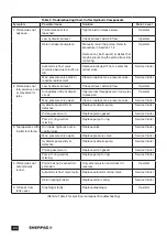
Table 1, Periodic Maintenance Chart
Time Interval
Maintenance Operation
Method
Maint. Level
Every 8 hours of
operation:
Check the cutter for loose,
damaged or worn parts.
Check for oil leaks. Tighten,
replace or repair as required.
Visual
Operator
Check the tightening
torque of screws and bolts.
Replace any missing screws
or bolts.
(Refer to instructions in Section 10.4)
Operator
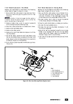
Check fixed and moving
blades for wear.
(Refer to instructions in Section 10.6.1) Operator
Every 1600 hours
of operation:
Change the hydraulic oil.
(Refer to instructions in Section 10.5.3) Service Center
As required:
Clean the cutter piston.
(Refer to instructions in Section 11.0)
Operator
Replace fixed and moving
blades.
(Refer to instructions in Section 10.6.2
and 10.6.3)
Operator
Summary of Contents for EBC20B
Page 25: ...25 Notes...
Page 26: ...26 Notes...
Page 27: ...27 Notes...
Page 28: ...199 Gateway Ct Columbus WI 53925 USA www enerpac com Made in Italy WWW ENERPAC COM...