

1
2
INSTALLATION INSTRUCTIONS
SPECIFICATIONS
DESCRIPTION
3
WARNING
Turn the POWER OFF at the circuit breaker before
installing the sensor
Read and understand these instructions before installing. This device
is intended for installation in accordance with the National Electric
Code and local regulations. It is recommended that a qualified
electrician perform
s
this installation. Make sure to turn off the circuit
breaker or fuse(s) and make sure power is off before wiring the device.
Use copper wires only.
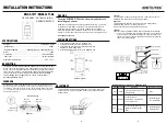
WIRING DIRECTIONS
As illustrated in Figure 1, The DWOS-1277 has a 180° detection range with a
maximum distance of 40’ detection in front of the sensor
and 20' on the sides
.
For maximum results, the sensor must be properly installed between the height
of 4’ to 5’ and away from obstructions such as walls, furniture and transparent
barriers like Low-E glass.
The DWOS-1277 uses advanced passive infrared sensor to detect heat emitted
motion. The sensor switch can turn on a load and keep it on as long as it detects
motion. The sensor will automatically shut off the load at the end of the selected
time delay. The countdown of the selected time delay starts after the last motion
detected. The sensor is customizable with dials that can adjust
Time Delay
,
detection
Range
, ambient
Light Level
, and
a switch to change between
Occupancy/ Vacancy
mode
s
.
1.
Connect RED wire from sensor to the LOAD wire.
2.
Connect BLACK wire from sensor to the HOT wire.
3.
Connect WHITE wire from sensor to the NEUTRAL wire.
NEUTRAL WIRE IS REQUIRED.
4.
Connect GREEN wire from sensor to the GROUND wire.
ADJUSTMENT
DWOS-1277 / DWOS-1277-NL
OCCUPANCY / VACANCY (2-IN-1)
SENSOR SWITCH
Incandescent .......................................................................… 800W
Time Delay..........................................................…… 15Sec to 30Mins
Light Level.................................................................... 30 Lux--Daylight
Fluorescent
/
Ballast......................800VA@120VAC /1600VA@277VAC
Operation Temperature...................................................... 32 F--131 F
Voltage .................................................................... 120/277VAC,60Hz
Motor ...................................................................................…… 1/4Hp
COVERAGE
Figure 1
Max. 20'
on the sides
Max. 40'
from front
Installation
Height: 4' - 5'
Detection Range
Wiring Diagram
Neutral
White
Hot
Black
Ground
Green
Load
Red
Load
Neutral
White
The control panel cover is also the push button on the switch.
Remove the
push-button
cover plate
by prying from the bottom of the
push-
button and
pulling outward.
Control Panel Cover
LED Indicator
OFF OCC VAC
TIME
TEST
Min
10
20
Min
30
Min
RANGE
LIGHT
3
3
2
Mounting
flange
Fresnel
Lens
OFF OCC VAC
4
1
2
4
1
(Push Button)
Time dial
This dial adjusts the time delay. Default position: 15 Seconds (Test mode)
Adjustable: from 15 Seconds to 30 Minutes (clockwise)
Range dial
This dial adjusts the detection range.
Default position: Center at 65%
Adjustable: 30% (Position 1) to 100% (Position 4).
Note: Use the greater setting for larger coverage area.
Light dial
The sensor may be adjusted to operate at the desired level of ambient light.
•
To do so, turn the dial to point the arrow toward the “-”sign for sensor to
detect motion and operate during low light or no light. Point the arrow
toward the “+”sign for sensor to operate when there’s more light in the
area or even during daylight.
OCC
Mod
e
OFF
VAC
Description
Circuit is permanently opened.
(switched off)
Occupancy Mode:
Automatic On, Automatic Off
after set time delay.
Position
Left
Center
Right
Vacancy Mode: Manual On only,
Automatic Off after set time
delay.
Push-button
Function
Manually toggles
None
Manually toggles
On / Off the load.
On/Off the load.
Off/ Occupancy/ Vacancy Mode Switch


