INSTALLATION / OPERATION USER’S MANUAL
NXD-1602M
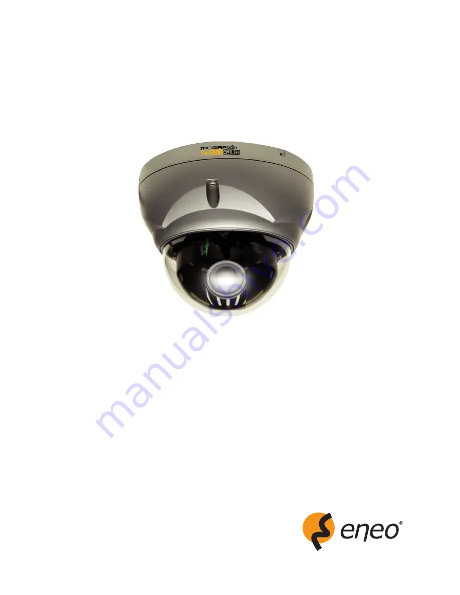
Full HD NETWORK CAMERA
www.hitron.co.kr
Page 1: ...INSTALLATION OPERATION USER S MANUAL NXD 1602M Full HD NETWORK CAMERA www hitron co kr ...
Page 2: ...ALIFIED SERVICE PERSONNEL Should any liquid or solid object fall into the cabinet unplug the unit and have it checked by the qualified personnel before operating it any further Unplug the unit from the wall oulet if it is not going to be used for several days or more To disconnect the cord pull it out by the plug Never pull the cord itself Allow adequate air circulation to prevent internal heat bu...
Page 3: ...F THIS EQUIPMENT IN A RESIDENTIAL AREA IS LIKELY TO CAUSE HARMFUL INTERFERENCE IN WHICH CASE THE USER WILL BE REQUIRED TO CORRECT THE INTERFERENCE AT HIS OWN EXPENSE CAUTION CHANGES OR MODIFICATIONS NOT EXPRESSLY APPROVED BY THE PARTY RESPONSIBLE FOR COMPLIANCE COULD VOID THE USER S AUTHORITY TO OPERATE THE EQUIPMENT THIS CLASS A DIGITAL APPARATUS COMPLIES WITH CANADIAN ICES 003 CET APPAREIL NUMÉ ...
Page 4: ...nce receptacles and the point where they exit from the apparatus 11 Only use attachments accessories specified by the manufacturer 12 Use only with the cart stand tripod bracket or table specified by the manufacturer or sold with the apparatus When a cart is used use caution when moving the cart apparatus combination to avoid injury from tip over 13 Unplug this apparatus during lightning storms or...
Page 5: ...16 Accessing the IP camera 16 Main Menu 17 LIVE VIEW 18 Live Video Page Icons 18 PLAYBACK 20 Playback View 20 SETUP 23 Users 24 Network 27 Image 29 Audio 31 Date Time 33 Live View Source 35 Image Basic 37 Image AE AWB 39 Image Day Night 41 Image WDR 3D DNR 43 Image Privacy Mask 46 Video Image Stream1 48 Video Image Stream2 50 Video Image Stream3 52 Video Image Stream4 55 Video Image Webcasting 58 ...
Page 6: ... Security Users 82 Security HTTPS 85 Security IP Filtering 87 Date Time 88 Network Basic 90 Network DDNS 92 Network RTP 93 Network UPnP 95 Network QoS 96 Language 97 Maintenance 98 Support 100 About 101 Technical Specifications 102 Image 102 Electrical Connector 102 Mechanical 102 Video 102 Audio 103 System Integration 103 Environmental 104 Physical 104 Troubleshooting 105 Upgrading the Firmware 1...
Page 7: ...eo Image Image Privacy Mask 46 Figure 23 Video Image Stream1 48 Figure 24 Video Image Stream2 50 Figure 25 Video Image Stream2 ROI setting 51 Figure 26 Video Image Stream3 52 Figure 27 Video Image Stream3 ROI setting 54 Figure 28 Video Image Stream4 55 Figure 29 Video Image Stream4 ROI setting 57 Figure 30 Video Image Webcasting 58 Figure 31 Audio Basic 59 Figure 32 Event Event In Alarm In 61 Figu...
Page 8: ... System Security HTTPS 85 Figure 54 System Security IP Filtering 87 Figure 55 System Date Time 88 Figure 56 System Network Basic 90 Figure 57 System Network DDNS 92 Figure 58 System Network RTP 93 Figure 59 System Network UPnP 95 Figure 60 System Network QoS 96 Figure 61 System Language 97 Figure 62 System Maintenance 98 Figure 63 System Support 100 Figure 64 About 101 ...
Page 9: ...mic Range Back Light Compensation function to view the object clearly in backlight conditions 3D DNR 3Dimensional Digital Noise Reduction technology dramatically cleans up the noise in video frames and solves the problem of low light sensitivity where it can display high image resolution even in extremely low light conditions DIS Digital Image Stabilization function minimizes the appearance of sha...
Page 10: ...tion When camera detects video motion or alarm events or manual trigger it can record video stream by itself Voice Alert Linked to Alarm Detection The NXD 1602M Series can play the audio file stored in the camera in synchronization with alarm detection by the sensor input or the motion detection function Network Flow Control The NXD 1602M Series provides a flow control function which enhances netw...
Page 11: ... for DC12V AC24V are not supplied Camera Layout Top View Lens Allows wide area to be monitored Connection Cable 26pin camera extension cable Connection Cable Main POWER connection RED DC12V or AC24V WHITE GND or AC24V ...
Page 12: ...nput 2 BROWN GND Light BLUE Alarm Out GRAY GND RJ 45 connection Connect Ethernet cable or supplies power to the camera if PoE is available BNC connection Connect BNC cable for composite video output SPEAKER connection GRAY Connect external speaker for audio output MIC connection BLACK Supplies external microphone as an audio input source ...
Page 13: ...work Starting Installation Base Installation 1 Make mounting holes and cable hole in the place ceiling to which this dome camera is installed using the supplied template sheet NOTE The total mass of the main unit is approx 1 3kg Check whether the ceiling to which the Dome Camera is installed is strong enough to hold the unit mass If not the Dome Camera could fall causing injury Figure 1 Mounting H...
Page 14: ... by turning and moving the hemisphere by hand 6 Lock the housing cover with torx screws 4x Figure 2 Lock Screw NOTES Cable through the electrical box with the dome base The housing can also be mounted on a 4s or 2s electrical box Using the conduit knockout punched with the dome base Remove the conduit knockout punched for the cable entry Figure 3 Mount electric box ...
Page 15: ...the controller board Figure 4 Heater Kit Installation NOTES Heater power consumption Power Supply AC24V DC12V Power Consumption 20Watt 10Watt Heater On at 41 F 5 C Heater Off at 59 F 15 C Use Certified Listed Class 2 power source only Micro SD Card Installation Optional 1 First open the housing cover and then check the SW2 mode whether SW2 is at off mode or not The default setting is off mode 2 In...
Page 16: ...ns for using web browser The minimum system requirements to use a Web browser with this IP camera are as follows CPU Pentium 4 microprocessor 2 0GHz Operational System Windows XP or Windows Vista or Windows7 System Memory RAM 512 Mbyte Ethernet 100 Mbit Video Resolution 1024 Horizontal x 768 Vertical pixels or higher Internet Explorer 7 or later ActiveX 2 0 0 9 or later Accessing the IP camera 1 O...
Page 17: ... Main Menu The dialog box will be appears Type User ID and Password in the dialog box The default User ID and Password are admin NOTE For security purposes be sure to change the password after you log on for the first time ...
Page 18: ...access the Setup menu and operate the main functions Figure 6 Main Live View Page Live Video Page Icons Hide Main Icons Hides main icons in the live view page Show Main Icons Shows main icons in the live view page Live view Displays live video stream Playback View Enters playback menu Setup Enters setup menu Help Shows helpful information ...
Page 19: ...gion of Interest Preset Specify the Preset This icon is inactivated if the PTZ settings are not set Pause Pause the live video stream Snapshot Take a picture of the video image currently on display Supports the origin image size view Print and Save feature Digital Zoom Supports a digital zoom in live video image Full Screen Expands video image to the entire screen area Manual Trigger Activates the...
Page 20: ...ser Figure 8 Playback View Event List Shows the recorded lists by Alarm Trigger and Motion event Event Search Select the start date and end date you want to playback and then click the Go button to show the list In case of you want to list up according to event type click the arrow button and select event type Calendar Shows the information about playback image Playback Control Buttons Provides us...
Page 21: ...rward play Fast forward play Go to the last Clip copy Digital Zoom Full Image Clip Copy Provides avi format file Please step as follows 1 Select Start Date Time and End Date Time 2 Set Export Path 3 Click Estimate button which is shown the file FPS and Size 4 Click Export or Cancel button ...
Page 22: ...me the following windows will be appeared Please retry to set the Start or End Date Time 3 In case of no image data between the Start Date Time and End Date Time the following windows will be appeared Please retry to set the Start or End Date Time 4 The buttons from to indicate an Hours and the number from 0 to 60 indicate a minutes ...
Page 23: ... to setup user dependent values and provide more advanced settings Basic Configuration Basic Configuration supply user to access the camera image using minimum setting Also it shows the camera basic information such as Model name Firmware version and MAC address Figure 9 Basic Configuration NOTE The setting menu might not be available if the user does not have the permission to access this feature...
Page 24: ... List Setting User accounts can be added or modified or removed The authority depends upon user group automatically and shows the permission status to access the menus The default user name password are admin User Name Shows the name which registered to access the camera User Group Shows the assigned permission given to users User Authority Shows the permission status to access the menus Click the...
Page 25: ...to 14 alphanumeric characters User names are not case sensitive 3 Click in the Password box and type a password 1 to 8 alphanumeric characters Passwords are case sensitive 4 Click in the Confirm password box and retype a password 5 Click in the User group box and select one of the groups you wish to assign to the user 6 Click the OK button to save the settings and add a new user ...
Page 26: ...group box and select one of the groups you wish to assign to the user 6 Click the OK button to save the settings and modify a user NOTE The user name can t be modified To remove a user 1 Select one of the User Name in the User List Setting you want to remove 2 Click the Remove button A dialog box appears with confirmation message 3 Click the OK button The user profile is removed from the User List...
Page 27: ...lect the choice box if you want to assign the IP address manually IP address The address of the camera connected to the network Specify a unique IP address for this network camera Subnet mask The address that determines the IP network that the camera is connected to relative to its address Specify the mask for the subnet the network camera is located on Default router The router that accesses othe...
Page 28: ...g are read only text Use the following DNS server address Select the choice box if you want to use the desired DNS server manually Domain name Enter the domain to search for the host name used by the network camera Primary DNS server Enter the IP address of the primary DNS server Secondary DNS server Enter the IP address of the secondary DNS server Click the Save button to save the settings or cli...
Page 29: ...rientation Figure 14 Basic Configuration Image Image Appearance The image appearance allows you to adjust the camera setting parameters and change the camera orientation All of parameters are recommended to be modifying for good image quality suitable for installation place ...
Page 30: ...the Save button Then D Zoom OSD windows will be appears and the Digital zoom is set to x1 1 automatically 2 Use Upper Direction or Lower Direction button to select an option then use Left Direction or Right Direction button to select a level ZOOM Use Left Direction or Right Direction button to enlarge the screen PAN Use Left Direction or Right Direction button to move the screen left or right TILT...
Page 31: ...efault setting is G 711 µ law Sample rate Indicates the number of times per second the sound is sampled The default setting is 8 kHz NOTE G 711 also known as Pulse Code Modulation PCM is a very commonly used waveform codec G 711 uses a sampling rate of 8 000 samples per second with the tolerance on that rate 50 parts per million ppm Non uniform quantization logarithmic with 8 bits is used to repre...
Page 32: ... if you do not want the audio input Audio Output Adjusts the audio volume especially to the Speaker Output volume The Output volume can be adjusted in the range from 18 1 to 6 0 dB The default setting is 0 dB Click the Mute box if you do not want the audio output Click the Save button to save the settings or click the Reset button to clear all of the information you entered without saving it ...
Page 33: ... your camera is located Click the Automatically adjust for daylight saving changes checkbox to automatically update the time changes caused by daylight saving Time zone The default setting is GMT Time mode The default setting is Set manually Synchronize with computer time Sets the time according to the clock on your computer Synchronize with NTP Server This option will obtain the correct time from...
Page 34: ...D Time Format The default setting is 24 hours Click the Save button to save the settings or click the Reset button to clear all of the information you entered without saving it Live View Use the Source tab to configure the live view video source and composite video output properties Source Configure the default live view source in the web browser and composite video output source ...
Page 35: ...w size Select one of the view sizes to be displayed in the live view page The default setting is a 1280x720 Stream type Select one of the stream protocols The default setting is UDP Default TV out Configure the composite video output properties Mode Select the composite video output format The default setting is NTSC Source Select one of the composite video output sources The default setting is st...
Page 36: ... back with normal video output mode NOTES The stream1 is only available stream source in Easy Focus mode While Easy Focus dwell time the stream1 is only transmitted the other streams does not transmit Click the Save button to save the settings or click the Reset button to clear all of the information you entered without saving it Video Image Use the Video Image tab to select a preset camera stream...
Page 37: ...es and orientation Figure 18 Video Image Image Basic Image Appearance The image appearance allows you to adjust the camera setting parameters and change the camera orientation All of parameters are recommended to be modifying for good image quality suitable for installation place ...
Page 38: ...ll be appears and the Digital zoom is set to x1 1 automatically 2 Use Upper Direction or Lower Direction button to select an option then use Left Direction or Right Direction button to select a level ZOOM Use Left Direction or Right Direction button to enlarge the screen PAN Use Left Direction or Right Direction button to move the screen left or right TILT Use Left Direction or Right Direction but...
Page 39: ... exposure settings Exposure mode Supports exposure modes to control the amount of light detected by the camera sensor base on settings for light conditions The default setting is ALC ALC Automatic Light Control for indoor scenes ELC Electronic Light Control for outdoor scenes White Balance Control White Balance Control defines how the camera processes video images to render true colors in a scene ...
Page 40: ...under the following conditions When the scene contains mostly high color temperature objects such as a blue sky or sunset When the scene is dim AWC_PUSH Auto White Balance Control If you select this mode you will be able to set up the White Balance by push triggered white valance in fixed mode White balance R gain Set the desired red value according to Indoor or Outdoor mode White balance B gain S...
Page 41: ...ct a mode for DAY NIGHT function Auto Day Night mode changes automatically Day Color mode enabled Night Black and white mode enabled NOTE If you set the AGC to OFF on the WDR BLC Control Web menu the Auto mode of the DAY NIGHT function is not available Transition Level Select a transition level The default setting is Middle Transition Time Select a transition time The default setting is 10 seconds...
Page 42: ... bright light is momentarily introduced in the scene For example when a car with its headlights turned on passes the camera scene Click the Save button to save the settings or click the Reset button to clear all of the information you entered without saving it Image WDR 3D DNR Use the WDR 3D DNR tab for clean monitoring images even in various camera installation environments ...
Page 43: ... inactivated automatically Mode Select a mode for WDR BLC function Off Not in use WDR Wide Dynamic Range feature can be very helpful to cope with very challenging lighting conditions It is capable of capturing both of the dark part and bright part and combining the differences into a scene to generate a highly realistic image as original scene BLC Back Light Compensation feature helps to alleviate...
Page 44: ... the HSBLC is activated by auto mode Level Select a level according to Mode selection AGC Select an AGC level according to Mode selection NOTE If you set AGC to OFF then the Day and Night Auto SENS UP and 3D DNR are not available Shutter speed Select a Shutter speed option X64 to X2 Set to the slow shutter Auto Adjust the shutter speed automatically Off Fix to the shutter speed AntiFlk Set the shu...
Page 45: ...low light conditions Level Select one of the 3D DNR levels Off Not in use High Select a High level Middle Select a Middle level Low Select a Low level Click the Save button to save the settings or click the Reset button to clear all of the information you entered without saving it Image Privacy Mask Use the Privacy Mask tab for aiming at the protection of personal privacy The selected part is not ...
Page 46: ...e Enter button for PRIVACY SETUP OSD menu REC CIR POL RECTANGLE 1 Use Left Direction or Right Direction button to select a mask on the MASK NUMBER 2 Use Left Direction or Right Direction button to set up the ON or OFF on the RECT DISPLAY option 3 Use Upper Direction or Lower Direction button to select an option then use Left Direction or Right Direction button to adjust the option HEIGHT Increase ...
Page 47: ...IUS SIZE You can adjust the RADIUS SIZE POLYGON 1 Use Left Direction or Right Direction button to select a mask on the MASK NUMBER 2 Use Left Direction or Right Direction button to set up the ON or OFF on the POLY DISPLAY option 3 Use Upper Direction Lower Direction Left Direction Right Direction and Enter buttons to draw the polygon by moving each vertex on the POLYGON DRAW Each movable spot each...
Page 48: ...over baseline profile include B slice type Baseline Primarily for low cost applications that requires additional error robustness such as video conferencing video over IP and mobile applications Tools used by baseline profile include I and P slice types Resolution Specified as the number of pixel columns width by the number of pixel rows height The Resolution can be adjusted in the range from 320x...
Page 49: ...e video stream as it maintains image quality throughput GOP structure Describes the composition of the video stream This GOP Group of Picture setting configures the number of partial frames that occur between full frames in the video stream For example in a scene where a door opens and a person walks through only the movements of the door and the person are stored by the video encoder The stationa...
Page 50: ...etting might not be obtainable due to programmed compression standard and processor power Bitrate Indicates the quality of the video stream rendered in kilobits per second The higher value means the higher video quality and bandwidth required The Compression can be adjusted in the range from 100 to 6000 kbps The default setting is 2000 kbps Frame rate Indicates the number of fps frame per second a...
Page 51: ...te place to locate the Content description Display timer Provides the device timer setting value The default setting is OFF ROI Setting ROI Region of Interest features that transmit the specially selected area in the primary stream using different channel resolution and frame rate Open ROI viewer Click the Open ROI viewer box and then appears the new popup window to assign the ROI stream Figure 25...
Page 52: ...Click the Save button to save the settings or click the Reset button to clear all of the information you entered without saving it Stream3 The Stream3 features the H 264 compression standard for ROI Figure 26 Video Image Stream3 H 264 Setting Configures the H 264 setting value for stream3 Profile Choose a profile The default setting is High High The primary profile for broadcast and disc storage a...
Page 53: ...width required The Compression can be adjusted in the range from 100 to 2000 kbps The default setting is 500 kbps Quality Automatically adjusts the compression rate to guarantee the image quality at only VBR mode The default setting is Middle Frame rate Indicates the number of fps frame per second available for the video stream configuration The Frame rate can be adjusted in the range from 1 to 30...
Page 54: ...rs Location Select the appropriate place to locate the Content description Display timer Provides the device timer setting value The default setting is OFF ROI Setting ROI Region of Interest features that transmit specially selected area in the primary stream using different channel resolution and frame rate Open ROI viewer Click the Open ROI viewer box and then appears the new popup window to ass...
Page 55: ...Click the Save button to save the settings or click the Reset button to clear all of the information you entered without saving it Stream4 The Stream4 features the H 264 compression standard for ROI Figure 28 Video Image Stream4 H 264 Setting Configures the H 264 setting value for stream4 Profile Choose a profile The default setting is High High The primary profile for broadcast and disc storage a...
Page 56: ...width required The Compression can be adjusted in the range from 100 to 2000 kbps The default setting is 500 kbps Quality Automatically adjusts the compression rate to guarantee the image quality at only VBR mode The default setting is Middle Frame rate Indicates the number of fps frame per second available for the video stream configuration The Frame rate can be adjusted in the range from 1 to 30...
Page 57: ... place to locate the Content description Display timer Provides the device timer setting value The default setting is OFF ROI Setting ROI Region of Interest features that transmit specially selected area in the primary stream using different channel resolution and frame rate Open ROI viewer Click the Open ROI viewer box and then appears the new popup window to assign the ROI stream Figure 29 Video...
Page 58: ... button to clear all of the information you entered without saving it Webcasting The NXD 1602M Series can stream live video to a website Copy the HTML code generated on the screen and paste it in page code of the website you want to display live video Figure 30 Video Image Webcasting Webcasting HTML code Supports 4 streams for webcasting service First selects one from the Stream1 to Stream4 and th...
Page 59: ...sic audio settings for the camera Compression type G 711 is the international standard for encoding wired telephone audio on 64kBit s channel It is a PCM Pulse Code Modulation scheme operating at 8 kHz sample rate The default setting is G 711 µ law Sample rate Indicates the number of times per second the sound is sampled The default setting is 8 kHz NOTES G 711 also known as Pulse Code Modulation ...
Page 60: ...els at lower signal levels Audio Input Adjusts the audio volume especially from the Mike Input volume The Input volume can be adjusted in the range from 21 00 to 21 00 dB The default setting is 0 dB Click the Mute box if you do not want the audio input Audio Output Adjusts the audio volume especially to the Speaker Output volume The Output volume can be adjusted in the range from 18 1 to 6 0 dB Th...
Page 61: ...arm In This page allows you to configure the 2 inputs supported by the camera Ports can be given as Normally Open or Normally Close state and their Normal state can be configured An input will be inactive as long as its Normal state equals its Current state The 2 options for Normal state are NO Normally Open and NC Normally Close The input is activated when the Current state changes so that it no ...
Page 62: ...nal hold on as an input signaling source Alarm In Port 2 Setting Click the Enable alarm in port2 checkbox to enable the Alarm In port 2 Type The default setting is NO NO Normally Open As an example if the Normal state for a pushbutton connected to an input is Open circuit this means that as long as the button is not pushed and the Current state remains as Open circuit the state will be inactive NC...
Page 63: ...indow Figure 33 Event Event In Manual Trigger Manual Trigger Setting Click the Enable manual trigger checkbox to enable manual trigger Dwell time The default setting is 60 seconds NOTE Dwell time means how long time the alarm output signal hold on as an output signaling source Click the Save button to save the settings or click the Reset button to clear all of the information you entered without s...
Page 64: ...t in the areas outside the selected windows will be ignored The camera can be configured with up to maximum 4 include windows Windows can be moved resized or deleted at any time The behavior for each window is defined by adjusting the Sensitivity Threshold and Motion dwell time The VMD feature is only available in the H 264 stream Figure 34 Event Event In VMD Stream1 Pre Viewer Provides live video...
Page 65: ...peat above step If you want to delete VMD area select one of the Windows title listed and then click the Remove button Windows title Click in the Windows title box and type for a window s title you are creating 1 to 31 alphanumeric characters Sensitivity Ordinary colored objects on ordinary backgrounds will trigger motion detection NOTE To only detect flashing light select a low sensitivity In oth...
Page 66: ...esized or deleted at any time The behavior for each window is defined by adjusting the Sensitivity Threshold and Motion dwell time The VMD feature is only available in the H 264 stream Figure 35 Event Event In VMD Stream3 Pre Viewer Provides live video image to configure VMD area Video Motion Detection Setting The following step describes how to configure the camera for motion detection First Clic...
Page 67: ...ndows title box and type for a window s title you are creating 1 to 31 alphanumeric characters Sensitivity Ordinary colored objects on ordinary backgrounds will trigger motion detection NOTE To only detect flashing light select a low sensitivity In other cases a high sensitivity level is recommended Threshold Object Size Only very large objects cause motion detection NOTE To avoid triggering on sm...
Page 68: ...esized or deleted at any time The behavior for each window is defined by adjusting the Sensitivity Threshold and Motion dwell time The VMD feature is only available in the H 264 stream Figure 36 Event Event In VMD Stream4 Pre Viewer Provides live video image to configure VMD area Video Motion Detection Setting The following step describes how to configure the camera for motion detection First Clic...
Page 69: ...ndows title box and type for a window s title you are creating 1 to 31 alphanumeric characters Sensitivity Ordinary colored objects on ordinary backgrounds will trigger motion detection NOTE To only detect flashing light select a low sensitivity In other cases a high sensitivity level is recommended Threshold Object Size Only very large objects cause motion detection NOTE To avoid triggering on sm...
Page 70: ...tication checkbox for use authentication to log in to this server Figure 37 Event Event Out SMTP Email SMTP Email Setting Click the Enable SMTP checkbox and provide the following information for SMTP Sender Click in the Sender box and enter the Email address as the sender Interval Enter the Email sending time interval after event occurred Aggregate events Enter the number of events for Email sendi...
Page 71: ...ser name as provided by your network administrator Password Enter the Password as provided by your network administrator Login method Select one for SMTP authentication method allowed NOTES If a PLAIN or LOGIN mechanism is negotiated the camera sends user name and password to the SMTP server The LOGIN mechanism is supported by Microsoft as well as by some other clients Most other clients support t...
Page 72: ...rator for more information on configuring email notification on your local network Click the Save button to save the settings or click the Reset button to clear all of the information you entered without saving it Event Out FTP JPEG Save the JPEG of the activated event to a defined FTP server Figure 38 Event Event Out FTP JPEG FTP Setting FTP notification will save a file on the specified FTP serv...
Page 73: ...ssword Enter the Password as provided by your network administrator NOTE If you permit to login FTP server by anyone without password click the Anonymous login checkbox JPEG Setting Configure the JPEG to send the FTP server Pre event Defines how many JPEG file will be made during 0 3 seconds before the event is generated Post event Defines how many JPEG file will be made during 0 3 seconds after t...
Page 74: ...he HTTP server and the script that will handle the request For example http 192 168 30 112 cgi bin upload cgi Port Enter the port number used by the HTTP server The Port number can be adjusted in the range 1 65535 The default setting is 80 User name Enter the user name used by the HTTP server Password Enter the password used by the HTTP server HTTP Server Test Enter the test message and click the ...
Page 75: ...efined audio data to external speaker Figure 40 Event Event Out Audio Alert Audio Alert Setting To use the audio alert function an audio data file made by user must be uploaded from your PC Provide the path to the file directly or use the Browse button to locate it Then click the Upload button An audio file for Audio Alert can be made by Audio Recorder tool in optional Nimra software Audio Alert T...
Page 76: ...sClient16 program All Programs Nimra Nimra in your PC the main window will be displayed as below Figure 41 Event Event Out Audio Alert Audio Recorder Click Tool in the menu of the main window and select Audio Recorder to start Audio Recorder Audio Recorder window will be appeared Figure 42 Event Event Out Audio Alert ARecoder window The description of each button in the ARecorder window follows Op...
Page 77: ...d then set the file name to save a current capture file with PCM format If you don t need to make any PCM file skip this step and then go to the step 5 directly 4 Click the Open button and then select the file name to open an audio file in PCM format 5 Click the Encode button to encode a current audio file to G 711 format for Audio Alert Set the file name and encode parameters Figure 43 Event Even...
Page 78: ...t event Enter post event time value for SD post recording Format Shows the SD card status and supports format functionality Device Status Check and notice below information before use 1 No Storage Shows that no SD card inserted 2 Unformatted Need to format SD card before use 3 Available Shows that SD card is ready to use 4 Device Locked need unlock Shows that current SD card was locked Unlock SD c...
Page 79: ...nation or send an email or active an output port Figure 46 Event Event Map Event Map List An event type is a set of parameters describing how the camera will perform certain actions Event type may be set up as Triggered according to requirements Event Name Shows the descriptive name provided by the user Event In Shows the source of event type as Alarm In 1 Alarm In 2 and VMD configured by the user...
Page 80: ...To add a new event map list select it and click the Add button Modify To modify an existing event map list select it and click the Modify button Remove To delete an event map list select it and click the Remove button Event Map Add Event Map page provides how to configure the event action if there is event triggering such as Alarm In and Manual trigger ...
Page 81: ...checkbox NOTE If you want to additional message when emailing click in the Subject Additional Info box and type a description for the text you are creating 0 to 255 alphanumeric characters FTP JPEG Click the FTP JPEG checkbox to enable the image uploading to FTP server using JPEG image HTTP Server Click the HTTP Server checkbox to enable the message sending to FTP server NOTE If you want to additi...
Page 82: ... clear all of the information you entered without saving it System The System tabs features various system information especially network security advanced network setting parameters system configurations and maintenance Security Users Use the Users tab to provide user permission to access the camera and lists User name and User Group accounting Figure 50 System Security Users User Setting Click t...
Page 83: ...permission status to access the menus Figure 51 System Security Users Add User To add a new user 1 Click the Add tab and then new pop up window appears 2 Click in the User name box and type a new user name 1 to 14 alphanumeric characters User names are not case sensitive 3 Click in the Password box and type a password 1 to 8 alphanumeric characters Passwords are case sensitive 4 Click in the Confi...
Page 84: ...roup box and select one of the groups you wish to assign to the user 6 Click the OK button to save the settings and modify a user NOTE The user name can t be modified To remove a user 1 Select one of the User Name in the User List Setting you want to remove 2 Click the Remove tab A dialog box appears with confirmation message 3 Click the OK button The user profile is removed from the User List Set...
Page 85: ...rotocol over SSL is a protocol used to provide the encrypted transmission Supports a URL that only starts with HTTPS HTTP HTTPS Supports both HTTP and HTTPS simultaneously You can access the camera using a standard HTTP URL but sensitive data is not encrypted during transmission To ensure that sensitive data is encrypted you must use a secure HTTPS URL NOTES To ensure security on the internet all ...
Page 86: ...cial certificate issued by a CA Certificate Authority must be uploaded from your PC Provide the path to the certificate directly or use the Browse button to locate it Then click the Upload button Installed Certificate In case of all the processing succeed the name of official certificate will be displayed and also its installed time NOTES Please refer to the home page of your preferred CA for info...
Page 87: ... function This dialog allows you to add new allowed denied IP addresses These can be added whole ranges subnets of IP address can be added directly On Off Click the checkbox to active the settings Priority Policy and IP ranges Priority The number means a priority if there are duplicated IP address each IP ranges Policy Determines the filtering attribute of the IP address selected Start IP Enters t...
Page 88: ...ed as an allowed address Click the Save button to save the settings or click the Reset button to clear all of the information you entered without saving it Date Time Use the Date and Time tab to set the camera s date and time values manually or automatically Figure 55 System Date Time Current Server Time Shows the current date and time Date The default setting is 1970 01 01 Time The default settin...
Page 89: ...with NTP Server This option will obtain the correct time from an NTP server every 60 minutes The NTP server s IP address or host name is specified in the time server Set manually Using this option allows you to manually enter the date and time Date Time Format Select one of the Date and Time format Date Format The default setting is YYYY MM DD Time Format The default setting is 24 hours Click the ...
Page 90: ...he IP address of the camera Network Basic Use the Network Basic tab to manage the network settings Figure 56 System Network Basic IP Address Configuration The DHCP Dynamic Host Configuration Protocol server has a feature that automatically assigns an IP address to the device if there is a device on the network ...
Page 91: ...to use the DNS server settings provided by the DHCP server automatically and then the remaining setting are read only text Use the following DNS server address Select the choice box if you want to use the desired DNS server manually Domain name Enter the domain to search for the host name used by the network camera Primary DNS server Enter the IP address of the primary DNS server Secondary DNS ser...
Page 92: ...ed to access it over the Internet Use the DDNS service to assign a host name for easy access to your network camera NOTES If the camera has not previously been registered at the Dynamic DNS Service you need the registration process first You will then need to visit http www security device name to complete the process If the camera is already registered at the Dynamic DNS Service and its IP addres...
Page 93: ... user password to be used for accessing the DDNS server Confirm password Enter user password again to confirm Maximum time interval Set the interval at which to regularly update the Dynamic DNS service The default setting is 10 minutes Register local network IP address Register a network camera IP address to the DDNS server Click the Save button to save the settings or click the Reset button to cl...
Page 94: ...dress does need to be changed please contact your network administrator Multicast destination IP Click in the Multicast destination IP box and type IP address NOTES Multicast addresses are allocated according to these IANA policies The default setting IP address is 231 1 128 20 RTP port The RTP port can be entered in the range 1024 65532 The default setting is 5000 NOTE The RTP port entered here m...
Page 95: ...e creating 1 to 32 alphanumeric characters If your computer is also enabled the camera is automatically detected and a new icon is added to Model Name MAC address NOTE UPnP must also be enabled on your Windows XP computer To do this open the Control Panel from the Start Menu and select Add Rename programs Select Add Remove Windows Components and open the Networking Services section Click Details a...
Page 96: ...rks the network traffic so that network routers know which service s to apply to the packet for example the amount of bandwidth reserved for the type of traffic The QoS in the NXD 1602M Series Network Camera marks the data packets belonging to various types of network traffic originating from the unit QoS enabled network routers and switches then use these markings to apply particular treatment to...
Page 97: ...n applications Click the Save button to save the settings or click the Reset button to clear all of the information you entered without saving it Language Use the Language tab to configure the language supported Figure 61 System Language Language Setting Provides the option of language supported Language The default setting is English Click the Save button to save the settings or click the Reset b...
Page 98: ...changing any of the setting Use this method if the unit is not behaving as expected Reset The unit is restarted and most current settings are reset to factory default values but the following settings does not reset The boot protocol DHCP or static The static IP address The default router The subnet mask The system time Default The Default button should be used with causion Pressing this returns t...
Page 99: ... automatically after the upgrade has completed 3 4 minutes After starting the upgrade process always wait about 3 4 minutes before restarting the camera even if you suspect the upgrade has failed Backup Save all parameters and user defined scripts to a backup file Backup Click the Backup button to take a backup of all the parameters and any user defined script Restore Use a saved backup file to re...
Page 100: ... diagnostic tool when troubleshooting System Log Provides information about system events Reports The Report contains important information about the server Server Report Provides information about the server status and should be included when requesting report Information be found here includes the camera s firmware version MAC address system information IP address and network connections Paramet...
Page 101: ... Here you can fine basic information about this camera Figure 64 About The About page shows basic information about this camera as follows Megapixel High Definition HD Network Camera Firmware version MAC address ...
Page 102: ...ard Power connector Terminal block for DC12V or AC24V input Power Input DC12V or AC24V or PoE IEEE802 3af Compliant Class2 Power Consumption PoE 120mA 5 9 W DC12V 430mA 5 2 W AC24V 460mA rms 6 1W Alarm Input Terminal block for two Alarm inputs Alarm Output Terminal block for one Alarm output Audio Input Output 3 5mm Microphone and 3 5mm Speaker out Day and Night True Day and Night IR Cut Filter Vi...
Page 103: ...ast Up to 10 simultaneously Multicast Unlimited users H 264 Security Access Multilevel Access Data Encryption Password protection IP filtering Features WDR 3D DNR DIS Privacy Mask ROI Easy Focus Digital PTZ VMD Image Effect Multiple Streaming AE AWB Snapshoot Manual Trigger Audio Mute Audio Alert Record and Playback Software Reset Remote Upgrade Audio Compression G 711 PCM 8 kHz μ law or A law Str...
Page 104: ...cal Camera Dimension H x Ø 120 mm x 154 mm Shipping Dimension H x W x D 190 mm x 190 mm x 195 mm Camera Weight 1000 g Shipping Weight 1300 g Included accessory Installation CD Accessory kit for installation Template sheet Extension connector kit NOTE Specifications are subject to change without notice ...
Page 105: ...ible Causes or Corrective Actions 1 The camera cannot be accessed by some clients If using a proxy server try disabling the proxy setting in your browser Check all cabling and connectors 2 The camera works locally but not externally Check if there are firewall settings that need to be adjusted Check if there are router settings that need to be configured 3 Poor or intermittent network connection I...
Page 106: ...ee if there is a firewall preventing viewing 13 Multicast H 264 only accessible by local clients Check if your router supports multicasting or if the router settings between the client and the server need to be configured The TTL value may need to be increased 14 Color saturation is different in H 264 and Motion JPEG Modify the settings for your graphics adapter Please see the adapter s documentat...
Page 107: ......
Page 108: ... distribution through specialised trade channels only Videor E Hartig GmbH Carl Zeiss Straße 8 63322 Rödermark Germany Tel 49 0 6074 888 0 Fax 49 0 6074 888 100 www videor com Technical changes reserved www eneo security com Copyright by Videor E Hartig GmbH 07 2012 ...