background image

15 

3   Operation  

The network camera can be used with Windows operating system and browsers. The 
recommended  browsers are Internet Explorer, Safari, Firefox, Opera and Google Chrome with 
Windows.  

NOTE:

 To view streaming video in Microsoft Internet Explorer, set your browser to allow  ActiveX 

controls.  


3.1   Access from a browser  

1. Start a browser (Internet Explorer).  

2. Enter the IP address or host name of the network camera in the Location/Address field of your 

browser.  

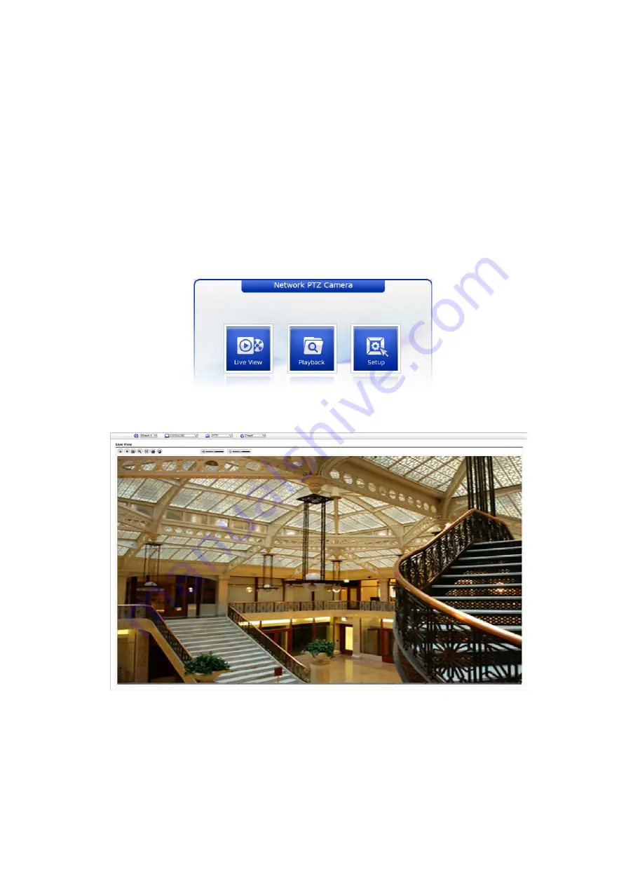
3. You can see a starting page. Click 

Live


View

Playback

, or 

Setup

 to enter web page.  


4. The network cameras Live View page appears in your browser.  


Summary of Contents for IPP-82A0030MIA

Page 1: ...EN User Manual 1 2 8 Network Dome 2MP 1920x1080 Day Night PTZ 4 3 129mm Infrared Outdoor IPP 82A0030MIA ...

Page 2: ... GRILLS OR OTHER OPENINGS ON THE EQUIPMENT CAUTION EXPLANATION OF GRAPHICAL SYMBOLS The lightning flash with arrowhead symbol within an equilateral triangle is intended to alert the user to the presence of uninsulated dangerous voltage within the product s enclosure that may be of sufficient magnitude to constitute a risk of electric shock to persons The exclamation point within an equilateral tri...

Page 3: ...d in accordance with the instruction manual may cause harmful interference to radio communications Operation of this equipment in a residential area is likely to cause harmful interference in which case the user will be required to correct the interference at his own expense CAUTION Changes or modifications not expressly approved by the party responsible for compliance could void the user s author...

Page 4: ...receptacles and the point where they exit from the apparatus 11 Only use attachments accessories specified by the manufacturer 12 Use only with the cart stand tripod bracket or table specified by the manufacturer or sold with the apparatus When a cart is used use caution when moving the cart apparatus combination to avoid injury from tip over 13 Unplug this apparatus during lightning storms or whe...

Page 5: ...ess from the internet 16 3 3 Setting the admin password over a secure connection 16 3 4 Live View Page 17 3 5 Playback 19 3 6 Network Camera Setup 21 3 6 1 Basic Configuration 21 3 6 2 Live View 25 3 6 3 Video Image 26 3 6 4 Audio 35 3 6 5 Event 36 3 6 6 Dome Configuration 61 3 6 7 System 70 3 7 Help 90 3 8 Resetting to the factory default settings 91 A Appendix 92 A 1 Troubleshooting 92 A 2 Alarm...

Page 6: ...ay store and retrieve a monitoring image by using a PC All the settings and real time monitoring screens are also provided through an access to the web The network camera is fully featured for security surveillance and remote monitoring needs It is based on the DSP compression chip and makes it available on the network as real time full frame rate Motion JPEG and H 264 video streams 1 1 Components...

Page 7: ... such as VCA Video Content Analysis The network camera s external inputs and outputs can be connected to devices such as sensors and relays enabling the system to react to alarms and activate lights or open close doors Improved Security The network camera logs all user access and lists currently connected users Also its full frame rate video can be provided over HTTPS Built in Synchronized IR LED ...

Page 8: ... the mounting base to wall using the supplied M8 tapping screw and plastic bushing Ceiling using the supplied M6 tapping screw and bushing 3 Wind the both thread of the pipe end with Teflon tape about 20 times for sealing Then use a silicone rubber sealant to seal the area where the wall ceiling mount and the pipe meet 4 Place a bead of silicone sealant around the wall and ceiling mount mounting f...

Page 9: ...nge 3 Pull out cables required to connect to the dome camera from the wall 4 Set and fix wall mount bracket using plastic anchors and M8x35 screws 5 Open the access plate and pull out cables through rectangular access hole of the wall mount bracket 6 Attach the 1 5 inch adapter to wall mount bracket and fix it using set screw 7 Attach the camera s safety wire to the wall mount bracket and organize...

Page 10: ... 3 Pull out cables required to connect to the dome camera from the ceiling 4 Attach the ceiling mount bracket using plastic anchors and screws 5 Attach 1 5 inch adapter to the pipe and fix it using set screw of the adapter 6 Pull out camera cables through the pipe and attach the camera to adapter and fix them using set screw of the adapter 7 After safety wire to the pipe to one of M6x35 screws of ...

Page 11: ...mpatible with 10 100Mbps 3 RCA BLACK AUDIO INPUT 4 RCA GRAY AUDIO OUTPUT 5 5 pin cable YELLOW ALARM INPUT 1 WHITE ALARM INPUT 2 VIOLET ALARM INPUT 3 BROWN ALARM INPUT 4 GRAY GND 6 2 pin cable RED ALARM OUTPUT BLACK GND The camera must be installed by qualified service personnel in accordance with all local and federal electrical and building codes ...

Page 12: ...ard Insertion User can install and change Micro SD card as shown in the following picture 1 Open the Micro SD card cover 2 Install or change Micro SD card 3 Tightly close the Micro SD card cover to ensure waterproofness ...

Page 13: ...onnectors G Ground NOTE All the connectors marked G or GND are common Connect the ground side of the alarm input and or alarm output to the G Ground connector AO Alarm Output The camera can activate external devices such as buzzers or lights Connect the device to the AO Alarm Output and G Ground connectors Connecting the Power PoE 12VDC Connect power of 12VDC for the camera When using a 12VDC adap...

Page 14: ...o use the program After pushing the button Find eneo devices you will get a list of cameras connected to the local network Highlight your camera in the list and open a context menu with a click of the right mouse button Select the Editing the camera IP address option to open a window for setting the cameras IP properties When you are done click the Activate button to update the camera settings For...

Page 15: ...w streaming video in Microsoft Internet Explorer set your browser to allow ActiveX controls 3 1 Access from a browser 1 Start a browser Internet Explorer 2 Enter the IP address or host name of the network camera in the Location Address field of your browser 3 You can see a starting page Click Live View Playback or Setup to enter web page 4 The network cameras Live View page appears in your browser...

Page 16: ...layed when the network camera is accessed for the setup at the first time Enter your admin name and password set by the administrator NOTE The default administrator user name and password is admin If the password is lost the network camera must be reset to the factory default settings Please see Resetting to the factory default settings To prevent network eavesdropping when setting the admin passw...

Page 17: ...deo stream on the Live View page Stream profiles are configured under Setup Basic Configuration Video Image For more information please see Basic Configuration Video Image of User s Manual The resolution drop down list allows you to select the most suitable one out of video resolutions to be displayed on Live View page The protocol drop down list allows you to select which combination of protocols...

Page 18: ...s a pop up window to manually start or stop the event The PTZ button activates a pop up window for Pan Tilt and Zoom control The VCA button shows hides VCA rule setting and detected objects The Face Detector button shows hides detected faces The Speaker button activates deactivates external speaker The Mic button activates deactivates microphone input Use this scale to control the volume of the sp...

Page 19: ...in the SD local storage select it from the list and click the Playback buttons Go to the first go to the beginning of the video clip Fast backward play fast play backward of the video clip Backward play play backward of the video clip Step backward play go back one frame of the video clip Pause pause playback of the video clip Step forward play go forward one frame of the video clip Forward Play p...

Page 20: ...played monthly If there is a recorded data for a particular date a blue square on the date will be displayed If you select a particular date in the calendar a yellow square on the date will be displayed 6 Play Time Displays time of the video playing 7 Event Search Window Select a search option in the drop down list and click GO button You can also enter the time period for searching If you click S...

Page 21: ... camera by clicking Setup either in the first connection page or the top second right button of the Live View page Accessing the network camera from a computer for the first time opens the Admin Password dialog box Enter your administrator or operator id and password to get into setup page NOTE If the password is lost the network camera must be reset to the factory default settings Please see Rese...

Page 22: ...vides the lowest level of access which only allows access to the Live View page Operator An operator can view the Live View page create and modify events and adjust certain other settings Operators have no access to System Options Administrator An administrator has unrestricted access to the Setup tools and can determine the registration of all other users Enable anonymous viewer login Check the b...

Page 23: ...static known IP address for a particular MAC address Use the following IP address To use a static IP address for the network camera check the radio button and then make the following settings IP address Specify a unique IP address for your network camera Subnet mask Specify the mask for the subnet the network camera is located on Default router Specify the IP address of the default router gateway ...

Page 24: ...Basic for more details about Video Image setup 4 Audio The network camera can transmit audio to other clients using an external microphone and can play audio received from other clients by attaching a speaker User can setup and change setting of Audio in this page Please refer to Audio for more details about Audio setup ...

Page 25: ...ll as determine Date Time format in this page Please refer to System Date Time for more details about Date Time setup 3 6 2 Live View Video Input Mode Video Mode Choose Video Mode you wish to use from the drop down list NTSC or PAL NOTE This function may not be applicable depending on the model ...

Page 26: ... service H 264 MP Main Profile Primary profile for low cost applications that require additional error robustness this profile is used rarely in videoconferencing and mobile applications it does add additional error resilience tools to the Constrained Baseline Profile The importance of this profile is fading after the Constrained Baseline Profile has been defined H 264 BP Baseline Profile Original...

Page 27: ... of Picture size If users want to have a high quality of fast image one by one please decrease the value For the purpose of general monitoring please do not change a basic value Such act may cause a problem to the system performance For the details of GOP setting please contact the service center Stream 2 Setting Sometimes the image size is large due to low light or complex scenery Adjusting the f...

Page 28: ...he camera movement stops and lasts for about 5 seconds Focus Limit Minimum distance for Auto Focus operation Object nearer than this limit may not be clearly focused Speed Focus speed can be adjusted in the range of 1 8 Sensitivity Focus sensitivity can be adjusted in the range of 1 3 NOTE Avoid continuous 24 hour use of the auto focus This will shorten the lifespan of the lens When the settings a...

Page 29: ...a can be streamed to a website User can copy and paste the HTML code generated on the screen to the website page code where user wants to display live video NOTE To use webcasting service the Enable Anonymous viewer login option must be checked ...

Page 30: ...30 4 Camera Setup In this page user can setup Exposure Control White Balance Control Image Appearance and Day Night control Video Preview User can check the setting via video preview pop up window ...

Page 31: ...ber Select Iris F number if Iris is in fixed mode 7 Enable high light compensation Activates HLC function 8 Level Determines HLC level 9 Enable backlight compensation Activates BLC function which cannot be used with WDR 10 Enable wide dynamic range Activates WDR which cannot be used with BLC or Defog function 11 Strength Determines WDR strength White Balance Control 1 Mode Select one of five white...

Page 32: ... Day Night Control User can setup Day Night operation mode among Automatic Day and Night Mode Automatic Normally displays color image and switches automatically to black white image after the ambient light level reaches a pre defined threshold Day Always displays color image Night Always displays black white image DN Threshold Adjusts the level of light which the camera automatically switches betw...

Page 33: ...mination is above the specified level the indicator will turn off 1 20 Fixed IR Bright Specify the brightness of the Fixed IR illuminator 1 5 Moving IR Bright Specify the brightness of the Moving IR illuminator 1 5 Delay The time duration for both of the lighting conditions can be customized to let the IR illuminators divert between activation and deactivation 1 60 Fixed IR Level Fixed IR illumina...

Page 34: ...tion of OSD on actual video via preview popup window OSD Setting User can determine show or hide OSD for each stream Also user can set the transparency level of OSD by slide bar or type in number OSD title User can show or hide OSD title and can change OSD title by type in The default is the model name of the camera Date Time User can show or hide date time on OSD NOTE The change in this page imme...

Page 35: ...the STEREO Jack I O of the network camera Input User can select amplifier between Internal Amp or External Amp Input volume If there are problems with the sound input being too low or high it is possible to adjust the input gain for the microphone attached to the network camera Audio Output Enable full duplex Check the box to enable Full Duplex mode This means that you can transmit and receive aud...

Page 36: ...a is started Select Enable on boot to activate the On Boot event Enter the Dwell time the event lasts from the point of detection 1 180 seconds When the settings are complete click Save button to save the settings or click Reset button to clear all of the information you entered without saving it ...

Page 37: ...to use an alarm port check the desired Enable alarm port first Type Choose the type of alarm to use from the drop down list NO Normally Open or NC Normally Closed Dwell Time Set the dwell time an event lasts from the point of detection of an alarm input When the settings are complete click Save button to save the settings or click Reset button to clear all of the information you entered without sa...

Page 38: ...vely the event can be triggered via the product s API Application Programming Interface Select Enable manual trigger to activate the manual trigger for up to 4 manual triggers Set the dwell time the trigger lasts When the settings are complete click Save button to save the settings or click Reset button to clear all of the information you entered without saving it ...

Page 39: ... sensitivity of this function where large value sets more sensitive detection Zone List ID Order of generation Include 1 8 Exclude 9 16 Name User definable zone name Type shows zone type and cannot be changed Threshold Determines how large the motion in the zone can trigger event in percentage Dwell time Determines how long the triggered event holds from the last triggering User can select any box...

Page 40: ...elect Enable network loss to activate the Network Loss event Select a dwell time for how long the event will last from the point of detection When the settings are complete click Save button to save the settings or click Reset button to clear all of the information you entered without saving it ...

Page 41: ...r move camera direction using external force Select Enable tampering to activate the Tampering event Dwell time Determine how long the event will last from the point of detection When the settings are complete click Save button to save the settings or click Reset button to clear all of the information you entered without saving it ...

Page 42: ...nsitivity Sensitivity As the value becomes bigger the detection sensitivity increases Min width size Minimum horizontal pixel size for detections in a 1920x1080 format Min height size Minimum vertical pixel size for detections in a 1920x1080 format Max width size Maximum horizontal pixel size for detections in a 1920x1080 format Max height size Maximum vertical pixel size for detections in a 1920x...

Page 43: ...lateral Rule Name User can type in the rule name Base The reference point of the object detection Mode Currently Enter rule only Exclusive Area The area where the rules are not applied Once selected a purple line appears on the video preview window Drag and drop the box at the desired position User can change the shape of the box by dragging each corner to any form of a quadrilateral NOTE Video Co...

Page 44: ... a bounding box for the detected face Select Enable face detector to activate the Face Detector Set threshold for detection sensitivity When the settings are complete click Save button to save the settings or click Reset button to clear all of the information you entered without saving it ...

Page 45: ... record status check Trigger event if the record status is modified Enable format event Trigger event if the micro SD card is formatted AIHM Server Setting Select Enable AIHM server to send the AIHM event to the AIHM server When the settings are complete click Save button to save the settings or click Reset button to clear all of the information you entered without saving it ...

Page 46: ...nction Enable specific time User can select type in date and time in the calendar for triggering the event Enable every day Trigger event every day at specified time Enable day of week Trigger event at the day of every week at specified time Enable month Trigger event at the selected date of every month at specified time When the settings are complete click Save button to save the settings or clic...

Page 47: ...the box is you are using a mail server to receive event notification and image email Mail Server Enter the host names or IP addresses for your mail server Port Enter the port number for your mail server Enable the sending of notifications and image email messages from the network camera to predefined addresses via SMTP Enable use SMTP authentication Check the box if your mail server requires authe...

Page 48: ...nter an email address and click the Test button to test that the mail servers are functioning and that the email address is valid When the settings are complete click Save button to save the settings or click Reset button to clear all of the information you entered without saving it ...

Page 49: ...s a firewall between the camera and the target FTP server Port Enter the port number used by the FTP server Remote directory Specify the path to the directory where the uploaded images will be stored If this directory does not already exist on the FTP server there will be an error message when uploading User name Password Provide your log in information Anonymous login Check the box if you want to...

Page 50: ...Configure as for pre event Prefix file name This name will be used for all the image files saved If suffixes are also used the file name will take the form prefix suffix extension Additional suffix Add either a date time suffix or a sequence number with or without a maximum value When the settings are complete click Save button to save the settings or click Reset button to clear all of the informa...

Page 51: ...put port Enable alarm out If selected the output becomes activated for as long as the event is active Type Select a type of NO Normally Open or NC Normally Closed When the settings are complete click Save button to save the settings or click Reset button to clear all of the information you entered without saving it ...

Page 52: ...se button to locate it Then click the Upload button Up to 3 audio files are available The total file size must be less than 512 KB Audio Alert Test When the setup is complete the audio output can be tested by clicking the Test button To remove an audio file select the file and click the Remove button NOTE For a proper operation of Audio Alert full duplex must be enabled in the Audio settings page ...

Page 53: ...a predefined preset position Check the box to enable the service and return to the Home position once the event has ended When the settings are complete click Save button to save the settings or click Reset button to clear all of the information you entered without saving it ...

Page 54: ...264 or MPEG 4 data Stream2 MJPEG data Stream3 H 264 or MPEG 4 data Pre event Enter pre event time value for the storage device pre recording Post event Enter post event time value for the storage device pre recording Record Schedule You can set the weekly recording schedule for each day Drag or click area by a box unit at first Clicking the block toggles the recording between on and off Click the ...

Page 55: ...like many other protocols builds on the Open Network Computing Remote Procedure Call ONC RPC system The CIFS screen displays as below Address Enter IP address for NAS device Remote Directory Enter directory or folder location to be recorded in the NAS device Capacity Enter the capacity of storage to be used This must be less than the total storage capacity ID Password Enter ID and Password The net...

Page 56: ... enable the service XML Notification Setting Notification server URL The network address to the server and the script that will handle the request Notification server port The port number of the notification server When the settings are complete click Save button to save the settings or click Reset button to clear all of the information you entered without saving it ...

Page 57: ... box to enable the service Boost Setting You can set the condition in Normal and Boost mode Boot Stream Select a video stream for each condition in the drop down list Frame rate Select a frame refresh rate per second for each condition in the drop down list Bit rate control Select VBR or CBR in the drop down list in Normal Condition You cannot change it in Boost Condition Bit rate Select a value f...

Page 58: ...can select message transmission type among HTTP HTTPS TCP and UTP URL The network address to the server and the script that will handle the request For example http 192 168 12 244 cgi bin upload cgi Port The port number of the server User name Password Provide your log in information Notification Server Test When the setup is complete the connection can be tested by clicking the Test button using ...

Page 59: ...amera up to a max 15 events can be registered Click the Add button to make a new event map a popup window displays as below To change an existing event select that event and click the Modify button this same window will display and the information can be changed as required Selecting an event and clicking Remove deletes the event ...

Page 60: ...ost When an event has occurred the camera will boost the Frame rate and Bit rate from the normal condition to this boosted level for the duration of the event Check the box to enable the Function PTZ preset Select the preset position you want to move at event If you want to move back to home position after the event which is pre defined in the Alarm Out PTZ Preset page check Return to home positio...

Page 61: ... Auto Focus is always active Manual Auto Focus is inactive Preset Setup Activate the PTZ Control Panel Preset Delete Delete selected Preset number Follow steps below to store the Preset positions 1 Click the Preset Setup button then shows the PTZ Control Panel 2 Choose the desired Preset number from the Preset drop down list 3 After aiming the camera view direction and lens control by using the Ar...

Page 62: ...Title Up to 12 characters Alphanumeric characters and space Repeat Select number of repetition from Continuous to 90 The default is Continuous Sequence Select either forward or backward sequence in the Tour position list Delete Tour Delete the stored Tour Position Setup list of Tour number Tour Position Setup Open or close the Tour Position Setup as below ...

Page 63: ...ion from Tour Position Setup list select the desired Tour Position and click the Delete Position button Set Position Click the Set Position button then show the stored Presets on drop down list Follow steps below to program the Tours 1 Click the desired Tour position of Tour Position Setup list and click Set Position button then show the saved Presets on drop down list Click a Preset 2 Repeat step...

Page 64: ...move pan tilt and zoom using Control box The movement history is automatically recorded 2 Click Done button after you completed the camera movement program 3 Repeat step 1 for each desired Pattern number 4 If you are not satisfied with the programed pattern click X button to clear the pattern 5 You can edit title of each pattern number for easier recognition NOTE 1 Each Pattern can store up to 500...

Page 65: ...ogramed Preset or Tour for function Function None Preset Tour Function No Select Preset or Tour number for Home Function Waiting Time 10 600 Seconds Function Use Off On When the settings are complete click Save button to save the settings or click Reset button to clear all of the information you entered without saving it ...

Page 66: ...elect On or Off Max Pan Speed The maximum pan speed can be adjusted in the range 1 38 Max Tilt Speed The maximum tilt speed can be adjusted in the range 1 30 When the settings are complete click Save button to save the settings or click Reset button to clear all of the information you entered without saving it ...

Page 67: ...l 90 vertically Auto When the camera reaches the floor directly above the moving object it will stop At that time release instantly and pull it down again to run the auto flip function When you use the panning range it is recommended to use the flip mode to Auto When the settings are complete click Save button to save the settings or click Reset button to clear all of the information you entered w...

Page 68: ...cute this origin check by clicking Origin Check button and the dome camera will return to the right position after the origin check operation Enable schedule origin check If selected execute origin check function at scheduled time Enable monthly Set specific day and time Enable weekly Set specific day of the week and time Enable daily Set specific time When the settings are complete click Save but...

Page 69: ...ing the Arrow and Zoom button in PTZ Control Panel click Set cell of Set column at any inactive row to create privacy zone 2 You can change the Title up to 12 alphanumeric characters 3 In order to hide or display the privacy zone choose On or Off in V off column 4 Click X at Delete column to delete privacy zone When the settings are complete click Save button to save the settings or click Reset bu...

Page 70: ...formation after installation Device Name Configuration Enter the device name Location Configuration Enter the location information You can enter up to four locations When the settings are complete click Save button to save the settings or click Reset button to clear all of the information you entered without saving it ...

Page 71: ...k the box to enable anonymous viewer login to the network camera without a user account When using the user account users have to log in at every access User List Setting This section shows how to register a user account Enter a user name and password to be added and register them by pressing the Add button You will see the pop up window as below When the settings are complete click Save button to...

Page 72: ... HTTP by default HTTP HTTPS HTTP HTTPS Upload Certificate To use HTTPS for communication with the network camera an official certificate issued by a CA Certificate Authority must be uploaded from your PC Provide the path to the certificate directly or use the Browse button to locate it Then click the Upload button Please refer to the home page of your preferred CA for information on where to send ...

Page 73: ...resses All other IP addresses not in this list will then be allowed or denied access accordingly that is if the addresses in the list are allowed then all others are denied access and vice versa Also see the online help for more information NOTE Users from IP addresses that will be allowed must also be registered with the appropriate access rights This is done from Setup System Security Users When...

Page 74: ...n setup Protocol type Port number LZO compression usage and Renegotiation time as well as download Server certificate file Choose Protocol type between UDP and TCP UDP is preferred Type in Port number you want to use default is 1194 Default Renegotiation time is 3600 seconds and 0 means no verification Use LZO compression determines whether to use cypher compression in connection or not CA certifi...

Page 75: ...setting Default Renegotiation time is 3600 seconds and 0 means no verification Upload CA certificate issued by Server 3 Select authentication method between User authentication and Machine authentication For Machine authentication upload client certificate and client key provided by Server For User authentication type in registered ID and Password 4 After finishing setup click Save button and then...

Page 76: ...r computer Synchronize with NTP Server The network camera will obtain the time from an NTP server every 60 minutes Set manually Allows you to manually set the time and date Date Time Format Specify the formats for the date and time 12h or 24h displayed in the video streams Select Date Time format from the drop down list Date Format Specify the date format YYYY Year MM Month DD Day Time Format Spec...

Page 77: ...se a static IP address for the network camera check the radio button and then make the following settings IP address Specify a unique IP address for your network camera Subnet mask Specify the mask for the subnet the network camera is located on Default router Specify the IP address of the default router gateway used for connecting devices attached to different networks and network segments IPv6 A...

Page 78: ...ost Name Enter the host name to be used as device information in the client software Services HTTP port Enter a port to receive a service through the HTTP Default port number is 80 HTTPS port Enter a port to receive a service through the HTTPS Default port number is 443 RTSP port Enter a port to receive a service through the RTSP Default port number is 554 ARP Ping Setting Enable ARP Ping setting ...

Page 79: ...ter an address of the DDNS server Username Enter an ID to access to the DDNS server Password Enter a password to be used for accessing the DDNS server Confirm Enter the password again to confirm it Maximum time interval Set a time interval to synchronize with the DDNS server Select the time interval from the drop down list Register local network IP address Register a Network Video Server IP addres...

Page 80: ...box to enable multicast operation Multicast destination IP Enter an IP between 224 0 0 0 and 239 255 255 255 RTP port Enter a value between 1024 and 65532 RTP TTL Enter a value between 1 and 255 If a network status is smooth enter a lower value However if a network status is poor enter a higher value When there are many network cameras or users a higher value may cause a heavy load to the network ...

Page 81: ...nP must be installed on your workstation if running Windows XP To do this open the Control Panel from the Start Menu and select Add Remove Programs Select Add Remove Windows Components and open the Networking Services section Click Details and then select UPnP as the service to add When the settings are complete click Save button to save the settings or click Reset button to clear all of the infor...

Page 82: ... router or switch which type of treatment to apply to this type of traffic for example how much bandwidth to reserve for it Note that DSCP values can be entered in decimal or hex form but saved values are always shown in decimal The following types of traffic are marked enter a value for each type of traffic used Live Stream DSCP Event Alarm DSCP Management DSCP Automatic Traffic Control Check the...

Page 83: ...re located on an intranet LAN and you wish to make it available from the other WAN side of a NAT router With NAT traversal properly configured all HTTP traffic to an external HTTP port in the NAT router is forwarded to the network camera NOTES For NAT port mapping to work this must be supported by the broadband router The broadband router has many different names NAT router Network router Internet...

Page 84: ...HCP and Domain Name System DNS or configure each computer s network settings manually which may be difficult and time consuming Zeroconf is built on three core technologies Assignment of numeric network addresses for networked devices link local address auto configuration Automatic resolution and distribution of computer hostnames multicast DNS Automatic location of network services such as printi...

Page 85: ...er a name in the Friendly name field NOTE Also known as zero configuration networking Bonjour enables devices to automatically discover each other on a network without having to enter IP addresses or configure DNS servers Bonjour is a trademark of Apple Computer Inc When the settings are complete click Save button to save the settings or click Reset button to clear all of the information you enter...

Page 86: ...language The language choices are English Korean French Russian and Chinese When the settings are complete click Save button to save the settings or click Reset button to clear all of the information you entered without saving it ...

Page 87: ...his will return all of the network camera s settings to the factory default values including the IP address Update Upgrade your camera by importing an upgrade file and pressing the Upgrade button During the upgrade do not turn off the power of the network camera Wait at least five minutes and then try to access the camera again Backup Save the setting values that users have entered to the network ...

Page 88: ...ck the Server Report button to get the important information about the server status this should always be included when requesting support Parameter List Click the Parameter List button to see the unit s parameters and their current settings Health Check System Check Click the System Check button to get the important information about the cameras system resources You can see the pop up window bel...

Page 89: ...89 Network Check Click the Network Check button to get the information about the cameras network setting and traffic You can see the pop up window below ...

Page 90: ...dow will be provided as a popup window so that users can open and read it without needing to log in It will offer a description of the setting and Help page so that users can manipulate the network camera without a reference to the manual ...

Page 91: ...s using the Reset button 1 Switch off the network camera by disconnecting the power adapter 2 Open the Micro SD card cover 3 Press and hold the Reset button SW1 on the board with your finger while reconnecting the power 4 Keep the Reset button SW1 pressed for about 2 seconds 5 Release the Reset button SW1 6 The network camera resets to factory defaults and restarts after completing the factory res...

Page 92: ...of images If images are very complex try limiting the number of clients accessing the camera Images only shown in black white Check the Video Image setting Blurred images Refocus the camera Poor image quality Increased lighting can often improve image quality Check that there is sufficient lighting at the monitored location Check all image and lighting settings Rolling dark bands or flickering in ...

Page 93: ...eventive maintenance allows detection and correction of minor that faults before they become serious and cause equipment failure Every three month perform the following maintenance 1 Inspect all connection cables for deterioration or other damage 2 Clean components with a clean damp cloth 3 Verify that all the mounting hardware is secure ...

Page 94: ...fps Video Streaming 50 60fps Dual Stream H 264 x 1 MJPEG x 1 25 30fps Triple Stream H 264 x 2 MJPEG x 1 Composite Out Audio Compression G 711 Audio Streaming 2 Way PTZ Function Pan Range 360 Endless Pan Speed Max 380 sec Preset Tilt Range 10 90 Tilt Speed Max 380 sec Preset Auto Calibration Preset 256 Tour 8 Pattern 8 Home Function Yes System Video Contents Analysis DIS Defog Face Detector Tamperi...

Page 95: ...d i OS External In Out Video Composite Out Audio 1 Input 1 Output RCA Mono Jack Alarm 4 Inputs 1 Output Ethernet RJ 45 10 100Base T µ SD Card SDHC Max 32GB RS485 ETC Operating Humidity 0 90 RH Non condensing Operating Temperature 30 65 Power Supply PoE Injector 12VDC Power Consumption 500mA 28 0W PoE 2 3A 28 0W 12VDC Dimensions See dimension Net Weight Approx 4 9kg Ingress Protection IP66 Specific...

Page 96: ... and some affect both If the load on the CPU reaches its maximum this will also affect the frame rate The following factors are among the most important to consider High image resolutions and or lower compression levels or high bitrates result in larger images Frame rate and Bandwidth affected Accessing both Motion JPEG and H 264 video streams simultaneously Frame rate and bandwidth affected Heavy...

Page 97: ...ribution through special ised trade channels only Videor E Hartig GmbH Carl Zeiss Straße 8 63322 Rödermark Germany Tel 49 0 6074 888 0 Fax 49 0 6074 888 100 www videor com www eneo security com Technical changes reserved Copyright by Videor E Hartig GmbH Version 02 2016 ...

Reviews: