background image

Prosonic S FDU90/91/91F/92/93/95/96

Hauser

11

Installation conditions for 
level measurements

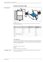
L00-FDU9xxxx-17-00-00-xx-003

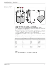
• If possible, install the sensor so that its lower edge projects into the vessel.
• Make sure, that the maximum level does not reach into the blocking distance (BD, see table).
• Do not install the sensor in the middle of the tank (2). We recommend leaving a distance (1) between the 

sensor and the tank wall measuring 1/6 of the tank diameter.

• Avoid measurements through the filling curtain (3).
• Make sure that equipment (4) such as limit switches, temperature sensors, baffles etc. are not located within 

the emitting angle 

. Emitting angles of the individual sensors are given in the table below. In particular, 

symmetrical equipment (5) such as heating coils etc. can influence the measurement.

• Align the sensor vertically to the product surface (6). An alignment unit (FAU40) is available as an accessory 

(

ä

31).

• If the two-channel version of the transmitter FMU90 or the multi-channel version of the transmitter FMU90 

is used, both sensors can be mounted in one vessel.

• To estimate the detection range, use the 3 dB emitting angle 

:

Warning!
All national guidelines applicable must be observed in explosion hazardous areas.

1

4

5

1/6D

r

a

L

BD

6

BD

2

3

D

BD

Sensor 

 (typically)

L (max)

r (max)

FDU90 12°

(9.8)

0.31 

(1.0)

FDU91 9°

10 

(33)

0.79 

(2.6)

FDU91F 12°

10 

(33)

1.05 

(3.4)

FDU92

11°

20 (66)

1.92 (6.3)

FDU93

25 (82)

0.87 (2.9)

FDU95

45 (148)

1.96 (6.4)

FDU96

70 (230)

3.6 (12)

m (ft)

Summary of Contents for Prosonic S FDU90

Page 1: ...m 148 ft in bulk materials FDU96 70 m 230 ft in bulk materials Suited for explosion hazardous areas Your benefits Non contact measurement method minimizes service requirements Integrated temperature s...

Page 2: ...Counter nut G 1 17 Dimensions FDU90 17 Dimensions FDU91 17 Dimensions FDU91F 18 Dimensions FDU92 18 Dimensions FDU93 18 Dimensions FDU95 19 Dimensions FDU96 19 Weight 19 Materials 20 Connecting cable...

Page 3: ...and reception From t and the velocity of sound c it calculates the distance D from the reference point see the figure 4 to the product surface D c t 2 From D results the desired measuring value Level...

Page 4: ...ement is not possible The blocking distance BD is dependent on the type of sensor L00 FDU9xxxx 05 00 00 xx 002 A Without flooding protection tube B With flooding protection tube C Reference point of t...

Page 5: ...e e g stirrers 10 to 20 dB foaming Please contact your Endress Hauser sales representative Bulk material surface Attenuation hard rough e g rubble 40 dB soft e g peat dust covered clinker 40 to 60 dB...

Page 6: ...10 residual ripple 100 mV 250 mA per sensor Note If the sensor heater is applied the integrated temperature sensor can not be used Instead an external temperature sensor Pt100 or FMT131 from Endress H...

Page 7: ...Colours of the strands YE yellow BK black RD red BU blue BN brown GNYE green yellow YE 9 12 BK 10 13 RD 11 14 FDU90 91 92 FDU80 80F 81 81F 82 BK YE RD 1 YE 9 12 BK 10 13 RD 11 14 FDU91F 93 95 96 FDU83...

Page 8: ...tance to the sensor does not exceed 30 m 98 ft Note For easier mounting it is advisable to use the sensors FDU90 91 92 and FDU80 80F 81 81F 82 with a maximum cable length of 30 m 98 ft as well For lon...

Page 9: ...the cable loosen the metallic braiding twist it together securely and connect it to the BK terminal Caution The protective earth conductor GNYE which is present in some of the sensor cables may not b...

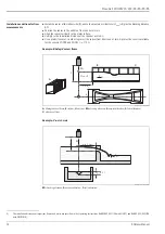
Page 10: ...to position the sensor over the centre of the flume Cantilever wall bracket and mounting frame are available as accessories 31 L00 FDU90xxxx 17 00 00 xx 001 A FDU90 Ceiling mounting B FDU90 Mounted at...

Page 11: ...ng angle Emitting angles of the individual sensors are given in the table below In particular symmetrical equipment 5 such as heating coils etc can influence the measurement Align the sensor verticall...

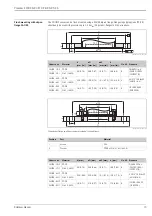
Page 12: ...ect the sensor from direct sun or rain A protective cover is available for the sensors FDU90 and FDU91 31 Example Khafagi Venturi flume L00 FDU9xxxx 17 00 00 xx 004 A Khafagi Venturi flume B inflow C...

Page 13: ...DIN2527 B FAU80 CAJ 316L 1 4435 FAU80 AAP PP FR 23 9 0 94 190 5 7 5 19 1 0 75 152 4 6 0 4 ANSI 3 150 lbs FF ANSI B 16 5 FAU80 AAJ 316L 1 4435 FAU80 KAP PP FR 18 0 71 185 7 28 19 0 75 150 5 9 8 JIS 10K...

Page 14: ...no burr on the inside of the tank side nozzle end Note the specified limits for nozzle diameter and length To minimise disturbing factors we recommend an angled socket edge ideally 45 L00 FDU9xxxx 17...

Page 15: ...ence echoes we recommend using an ultrasound guide pipe e g PE or PVC wastewater pipe with a minimum diameter of DN80 for FDU90 DN100 for FDU91 DN200 for FDU92 Make sure that the pipe is not soiled by...

Page 16: ...C 40 to 176 F 1 1 In order to avoid ice build up the sensors FDU90 and FDU91 are available in a version with integrated sensor heater 6 If this heater is used an external temperature sensor has to be...

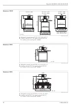
Page 17: ...00 FDU91xxx 06 00 00 xx 001 A Cable gland for approval versions FDU91 C D E G H J R U V 1 B Conduit connection NPT 1 2 for approval versions FDU91 Q S The conduit connection is partly potted half fill...

Page 18: ...S The conduit connection is partly potted half filled Dimensions FDU93 L00 FDU93xxx 06 00 00 xx 001 A Cable gland for approval version FDU93 C D E G H J R U W 1 B Conduit connection NPT 1 2 for approv...

Page 19: ...1 B Conduit connection NPT 1 2 for approval versions FDU96 K L P T The conduit connection is partly potted half filled Weight 170 6 69 235 9 25 A B G 1 NPT 1 28 1 1 25 1 0 26 1 0 mm in 450 17 7 198 7...

Page 20: ...of the sensors must be checked before installation with compatibility charts Pos Part FDU90 FDU91 FDU91F FDU92 1 Sensor housing PVDF 316L 1 4404 1 4435 PVDF 2 Counter nut PA6 6 PA6 6 3 Cable gland PA...

Page 21: ...cable extension cable must not exceed 300 m 984 ft Pos Part FDU93 FDU95 FDU96 1 Sensor UP Unsaturated polyester resin 2 Cable gland CuZn nickel plated 3 Adpater CuZn nickel plated 4 O ring VMQ 5 Seali...

Page 22: ...are suitably qualified Observe the specifications in the certificate as well as national and local standards and regulations The transmitter may only be installed in suitable areas Sensors with a cer...

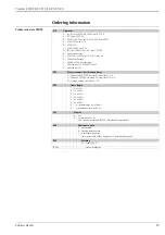
Page 23: ...5 DIP A20 21 IP65 2 NEPSI Ex ma II T5 020 Process connection threaded boss G Thread ISO228 PVDF rear side G1 front side G1 1 2 N Thread ANSI PVDF rear side NPT1 front side NPT1 1 2 W Ceiling mounting...

Page 24: ...ose V TIIS Ex is IIC T6 1 NEPSI Ex ma II T6 DIP A20 21 IP65 2 NEPSI Ex ma II T6 020 Process connection threaded boss G Thread ISO228 G1 PVDF N Thread ANSI NPT1 PVDF 030 Cable length 1 5 m 16 ft 2 10 m...

Page 25: ...ma II T6 DIP A20 21 IP65 2 NEPSI Ex ma II T6 020 Process connection F for slip on flange 316L accessory FAU80A G Thread ISO228 G1 316L N Thread ANSI NPT1 316L S Tri Clamp ISO2852 DN101 6 4 316L 3A T...

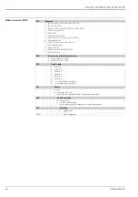
Page 26: ...II III Div 1 2 Gr A G zone 1 2 U CSA General Purpose V TIIS Ex is IIC T6 1 NEPSI Ex ma II T6 DIP A20 21 IP65 2 NEPSI Ex ma II T6 020 Process connection threaded boss G Thread ISO228 G1 PVDF N Thread A...

Page 27: ...III Div 1 Gr E G zone 2 U CSA General Purpose W TIIS dust Ex DP12 in preparation 1 NEPSI DIP A20 21 IP65 2 NEPSI Ex ma II T6 DIP A20 21 IP65 020 Process connection threaded boss G Thread ISO228 G1 UP...

Page 28: ...DIP A20 21 IP65 2 NEPSI Ex ma II T6 DIP A20 21 IP65 015 Temperature blocking distance material 1 40 80 C 176 F 70 cm 2 3ft membrane 316L PEcoated 2 40 150 C 302 F 90 cm 2 9ft membrane 316L 020 Proces...

Page 29: ...ure 40 140 C 284 F zone 2 21 22 R Non hazardous area T CSA Cl II III Div 1 Gr E G HT Ambient temperature 40 140 C 284 F zone 2 U CSA General Purpose W TIIS dust Ex DP12 in preparation 1 NEPSI DIP A20...

Page 30: ...pe of delivery Instrument according to the version ordered This Technical Information TI00396F 00 EN serves as installation and operating instruction For certified instrument versions Safety Instructi...

Page 31: ...for FDU90 and FDU91 for Sensor Material Cable type Order code FDU90 FDU91 FDU92 PVC LiYCY 2x 0 75 71027742 FDU91F FDU93 FDU95 PVC 40 to 105 C 40 to 221 F LiYY 2x 0 75 D 1x0 75 71027743 FDU95 FDU96 Sil...

Page 32: ...4bar abs 58psia suitable for 3 150lbs DN80 PN16 10K 80 XJJ UNI flange 3 DN80 80 316L max 4bar abs 58psia suitable for 3 150lbs DN80 PN16 10K 80 XKF UNI flange 4 DN100 100 PVDF max 4bar abs 58psia suit...

Page 33: ...htness the supplied gasket has to be applied and the flooding protection tube must be screwed hand tight up to limit stop When re equipping the flooding protection tube repeat the basic setup includin...

Page 34: ...mm 1 38 in orifices are for the sensors FDU9x The 22 mm 0 87 in orifice may be used for an external temperature sensor e g FMT131 Fixing screws are supplied 3 1 2 A B 1 A B C D Material Weight Order...

Page 35: ...l 4 9 kg 10 08 lbs 919791 0002 1400 55 1 316Ti 1 4571 919791 0003 mm in Material Weight Order Code galv steel 1 4 kg 3 09 lbs 919792 0000 316Ti 1 4571 919792 0001 3 2 0 13 20 0 8 55 2 17 100 3 94 25 0...

Page 36: ...ng mounting L00 FDU9xxxx 00 00 00 xx 001 Suited for sensors Material Order No FDU90 FDU91 FDU91F FDU92 316L 1 4404 71093130 185 7 28 5 0 2 15 0 59 15 0 59 50 1 97 10 0 39 95 3 74 35 1 38 12 0 47 10 0...

Page 37: ...must be used for applications in ATEX zone 20 7 Screw for lateral movement 18 Nm 2 13 276 lbf ft 8 Mounting grooves present in the UNI flange The alignment unit can be rotated up to 15 For further in...

Page 38: ...ng on the instrument version the following operating instructions are supplied with the Prosonic S FMU90 These operating instructions describe installation and commissioning of the respective version...

Page 39: ...ons ATEX FDU90 J FDU91 J FDU91F J FDU92 J II 2 G Ex ma IIC T5 Gb FDU90 II 2 G Ex ma IIC T6 Gb FDU91 91F 92 XA00321F FDU90 E FDU91 E FDU91F E FDU92 E FDU93 J FDU95 J FDU96 J II 2 G Ex ma IIC T5 Gb FDU9...

Page 40: ...al Endress Hauser Instruments International AG Kaegenstrasse 2 4153 Reinach Switzerland Tel 41 61 715 81 00 Fax 41 61 715 25 00 www endress com info ii endress com TI00396F 00 EN 15 12 71197998 FM SGM...

Reviews: