background image

Proline 200 FOUNDATION Fieldbus

Electrical connection

Hauser

19

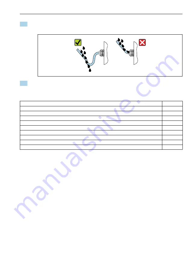
5. To ensure that moisture does not enter the cable entry:

Route the cable so that it loops down before the cable entry ("water trap").

  A0029278

6. Insert dummy plugs into unused cable entries.

5.4  

Post-connection check

Are cables or the device undamaged (visual inspection)?

Do the cables used meet the requirements→   12?

Do the cables have adequate strain relief?

Are all the cable glands installed, firmly tightened and leak-tight? Cable run with "water trap" →   18?

Depending on the device version: are all the device plugs firmly tightened →   16?

Does the supply voltage match the specifications on the transmitter nameplate →   15?

Is the terminal assignment correct ?

If supply voltage is present, do values appear on the display module?

Are all housing covers installed and firmly tightened?

Is the securing clamp tightened correctly?

Summary of Contents for Proline 200 FOUNDATION Fieldbus

Page 1: ...iolis sensor These instructions are Brief Operating Instructions they are not a substitute for the Operating Instructions pertaining to the device Transmitter Brief Operating Instructions Contain info...

Page 2: ...oline 200 FOUNDATION Fieldbus 2 Endress Hauser Order code Ext ord cd Ser no www endress com deviceviewer Endress Hauser Operations App XXXXXXXXXXXX XXXXX XXXXXX XXX XXXX XX Serial number 1 3 2 A002355...

Page 3: ...ct identification Storage and transport Installation Transmitter Brief Operating Instructions The Transmitter Brief Operating Instructions are aimed at specialists with responsibility for commissionin...

Page 4: ...11 5 Electrical connection 12 5 1 Connection conditions 12 5 2 Connecting the measuring device 16 5 3 Ensuring the degree of protection 18 5 4 Post connection check 19 6 Operation options 20 6 1 Over...

Page 5: ...symbol contains information on procedures and other facts which do not result in personal injury 1 1 2 Symbols for certain types of information Symbol Meaning Symbol Meaning Permitted Procedures proce...

Page 6: ...t grounding system 1 1 4 Communication symbols Symbol Meaning Symbol Meaning Wireless Local Area Network WLAN Communication via a wireless local network LED Light emitting diode is off LED Light emitt...

Page 7: ...ure that the measuring device remains in proper condition for the operation time Keep within the specified pressure and temperature range Only use the measuring device in full compliance with the data...

Page 8: ...king due to measuring tube breakage If a measuring tube ruptures the pressure inside the sensor housing will rise according to the operating process pressure Use a rupture disk LWARNING Danger from me...

Page 9: ...ction for the device and associated data transfer must be implemented by the operators themselves in line with their security standards 2 7 Device specific IT security The device offers a range of spe...

Page 10: ...tment cover using an Allen key 2 Unscrew cover of the electronics compartment from the transmitter housing 3 Optional pull out the display module with a gentle rotational movement 4 Turn the display m...

Page 11: ...mitter post installation check The post installation check must always be performed after the following tasks Turning the transmitter housing Turning the display module Is the device undamaged visual...

Page 12: ...that apply in the country of installation must be observed The cables must be suitable for the minimum and maximum temperatures to be expected Signal cable Pulse frequency switch output Standard inst...

Page 13: ...tput 1 Output 2 1 2 3 4 Option E 1 2 FOUNDATION Fieldbus Pulse frequency switch output passive 1 Output 1 must always be used output 2 is optional 2 FOUNDATION Fieldbus with integrated reverse polarit...

Page 14: ...peration when EMC interference is present These measures have been taken into account for this device Operation in the event of disturbance variables as per NAMUR NE21 is thus guaranteed 1 Observe nat...

Page 15: ...observe cable specifications 4 T box 5 Measuring device 6 Local grounding 7 Bus terminator 8 Potential equalization conductor 5 1 6 Requirements for the supply unit Supply voltage Transmitter An exter...

Page 16: ...cable 3 If the measuring device is supplied with cable glands Observe requirements for connecting cables 12 5 2 Connecting the measuring device NOTICE Limitation of electrical safety due to incorrect...

Page 17: ...ight sealing do not remove the sealing ring from the cable entry 4 Strip the cable and cable ends In the case of stranded cables also fit ferrules 5 Connect cable in accordance with terminal assignmen...

Page 18: ...ation are required For devices intended for use in hazardous locations please observe the guidelines in the Ex documentation XA 5 3 Ensuring the degree of protection The measuring device fulfills all...

Page 19: ...o the cables used meet the requirements 12 Do the cables have adequate strain relief Are all the cable glands installed firmly tightened and leak tight Cable run with water trap 18 Depending on the de...

Page 20: ...of operation options 1 2 3 4 E ESC 5 6 A0032226 1 Local operation via display module 2 Computer with operating tool e g FieldCare DeviceCare AMS Device Manager SIMATIC PDM 3 Field Xpert SFX350 or SFX...

Page 21: ...for operators and maintenances Operator Maintenance task oriented function oriented Expert A0014058 EN 2 Schematic structure of the operating menu 6 2 2 Operating philosophy The individual parts of th...

Page 22: ...e type measuring channel number symbol for diagnostic behavior 1 4 Status area 1 5 Measured value 1 6 Unit for the measured value 1 7 Operating elements 2 Operational display with measured value shown...

Page 23: ...ion view Status area Display area The following appears in the status area of the navigation view in the top right corner In the submenu The direct access code for the parameter you are navigating to...

Page 24: ...selected action Pressing the key for 2 s Confirms the edited parameter value Minus key In a menu submenu Moves the selection bar upwards in a choose list With a wizard Confirms the parameter value an...

Page 25: ...ization Disabling write protection via access code Enabling and disabling the keypad lock 6 4 Access to the operating menu via the operating tool The operating menu can also be accessed via the FieldC...

Page 26: ...operational display If nothing appears on the local display or a diagnostic message is displayed refer to the Operating Instructions for the device 2 8 3 Setting the operating language Factory settin...

Page 27: ...e device version e g sensor Wizard Meaning Select medium Define the medium Pulse frequency switch output Configure the selected output type Analog inputs Configure the analog inputs Display Configure...

Page 28: ...entional modification Protect access to parameters via access code Protect access to local operation via key locking Protect access to measuring device via write protection switch Protect access to pa...

Page 29: ...ly voltage Supply voltage A0029431 EN 5 Message about remedial measures 1 Diagnostic information 2 Short text 3 Service ID 4 Diagnostic behavior with diagnostic code 5 Operation time of occurrence 6 R...

Page 30: ......

Page 31: ......

Page 32: ...www addresses endress com...

Reviews: