background image


19 

AUTORANGING/MANUAL RANGE SELECTION 

When the meter is first turned on, it automatically goes into 
AutoRanging. This automatically selects the best range for the 
measurements being made and is generally the best mode for most 
measurements. For measurement situations requiring that a range 
be manually selected, perform the following: 

1. Press the 

RANGE

 key. The “

AUTO”

 display indicator will turn off. 

2.  Press the 

RANGE

 key to step through the available ranges until 

you select the range you want. 

3.  To exit the Manual Ranging mode and return to Autoranging, 

press 

EXIT


Note:

 Manual ranging does not apply for the Temperature functions. 


MAX/MIN 

1. Press the 

MAX/MIN

 key to activate the MAX/MIN recording mode. 

The display icon "

MAX

" will appear. The meter left auxiliary 

display will display and hold the maximum reading and will update 
only when a new “max” occurs. The display icon "

MIN

" will appear. 

The right auxiliary display meter will display and hold the 
minimum reading and will update only when a new “min” occurs. 

2.To exit MAX/MIN mode press 

EXIT 

RELATIVE MODE 

The relative measurement feature allows you to make 
measurements relative to a stored reference value. A reference 
voltage, current, etc. can be stored and measurements made in 
comparison to that value. The displayed value is the difference 
between the reference value and the measured value. 

Note:


Relative mode does not operate in the 4-20mA function. 

1.  Perform the measurement as described in the operating 

instructions. 

2.  Press the

 REL

 button to store the reading in the display and the   

"

REL

" indicator will appear on the display. 

Summary of Contents for ET2144

Page 1: ...User s Guide ET2144 True RMS Industrial Multimeter...

Page 2: ...1...

Page 3: ...a potentially hazardous situation which if not avoided could result in death or serious injury This CAUTION symbol indicates a potentially haza rdous situation which if not avoided may result da mage...

Page 4: ...nsuming equipment to be supplied from the fixed installation Note Examples include household office and laboratory appliances OVERVOLTAGE CATEGORY III Equipment of OVERVOLTAGE CATEGORY III is equipmen...

Page 5: ...30 seconds max every 15 minutes Frequency Resistance Capacitance Duty Cycle Diode Test Continuity 1000V DC AC rms Temperature 1000V DC AC rms Surge Protection 8kV peak per IEC 61010 2 USE EXTREME CAU...

Page 6: ...anner not specified by the manufacturer the protection provided by the equipment may be impaired Controls and Jacks 1 40 000 count LCD display 2 MAX MIN button 3 STORE RECALL button 4 RANGE SETUP butt...

Page 7: ...Hertz frequency V Volts Percent duty ratio REL Relative AC Alternating current AUTO Autoranging DC Direct current HOLD Display hold F Degrees Fahrenheit C Degrees Centigrade MAX Maximum MIN Minimum N0...

Page 8: ...to a higher range DC VOLTAGE MEASUREMENTS CAUTION Do not measure DC voltages if a motor on the circuit is being switched ON or OFF Large voltage surges may occur that can damage the meter 1 Set the fu...

Page 9: ...or OFF Large voltage surges may occur that can damage the meter 1 Set the function switch to the green VAC Hz position 2 Insert the black test lead banana plug into the negative COM jack Insert red t...

Page 10: ...position 2 Press the MODE button to indicate DC or AC or in AC range press EXIT for two seconds and chose AC DC 3 Insert the black test lead banana plug into the negative COM jack Insert the red test...

Page 11: ...DC set the function switch to the yellow mA position and insert the red test lead banana plug into the A mA jack 4 For current measurements up to 20A DC set the function switch to the yellow 10A HZ po...

Page 12: ...A mA jack 4 For current measurements up to 20A AC set the function switch to the yellow 10A HZ position and insert the red test lead banana plug into the 10A jack 5 Press the MODE button to indicate A...

Page 13: ...s Remove the batteries and unplug the line cords 1 Set the function switch to the green CAP position 2 Insert the black test lead banana plug into the negative COM jack Insert the red test lead banana...

Page 14: ...check 5 If the resistance is less than approximately 35 the audible signal will sound If the circuit is open the display will indicate OL DIODE TEST 1 Set the function switch to the green CAP positio...

Page 15: ...ds to the capacitor to be tested Read the capacitance value in the Display TEMPERATURE MEASUREMENTS 1 Set the function switch to the green Temp position 2 Insert the Temperature Probe into the input j...

Page 16: ...A 25 4mA 0 20mA 100 and 24mA 125 INSULATION RESISTANCE MEASUREMENTS a Set the rotary function switch to the INSULATION position and Press the RANGE button to chose one of the voltage which display on...

Page 17: ...ically from testing status during the process POWER TOOLS AND AMALL APPLIANCES This test would also apply to other similar equipment that has a line cord For double insulated power tools the megohmmet...

Page 18: ...coils and armature connect one megohmmeter lead to the grounded motor housing and the other lead to the brush on the commutator If the resistance measurement indicates a weakness raise the brushes of...

Page 19: ...from other equipment Check each conductor to ground and or lead sheath by connecting one megohmmeter lead to a ground and or lead sheather and the other megohmmeter lead to each of the conductors in t...

Page 20: ...rding mode The display icon MAX will appear The meter left auxiliary display will display and hold the maximum reading and will update only when a new max occurs The display icon MIN will appear The r...

Page 21: ...n captures the peak AC or DC voltage or current The meter can capture negative or positive peaks as fast as 1 millisecond in duration Momentarily press the PEAK button PEAK and MAX will display in lef...

Page 22: ...nt to clean all the memory data the steps are When power on press the EXIT button long time and then turn the switch from OFF to random and release the EXIT button the LCD will flash thrice and meanti...

Page 23: ...o exit LOW BATTERY INDICATION When the icon appears alone in the display the battery should be replaced Maintenance WARNING To avoid electric shock disconnect the test leads from any source of voltage...

Page 24: ...INSTALLATION WARNING To avoid electric shock disconnect the test leads from any source of voltage before removing the battery cover 1 Turn power off and disconnect the test leads from the meter 2 Open...

Page 25: ...the battery 4 Remove the six A screws securing the rear cover 5 Gently remove the old fuse and install the new fuse into the holder 6 Always use a fuse of the proper size and value 0 5A 1000V fast bl...

Page 26: ...ltage 50 to 1000Hz 400mV 0 1mV 1 0 reading 7digits 4V 0 001V 40V 0 01V 1 0 reading 5 digits 400V 0 1V 1000V 1V AC DCVoltag e 400mV 0 1mV 1 0 reading 7digits 50 60HZ 4V 0 001V 40V 0 01V 400V 0 1V 1000V...

Page 27: ...7digits 4000 A 1 A 40mA 0 01mA 400mA 0 1mA 10A 0 01A 20A 30 sec max with reduced accuracy All AC current ranges are specified from 5 of range to 100 of range NOTE Accuracy is stated at 65 o F to 83 o...

Page 28: ...ing 10 digits 40mF 0 001mF Frequency electronic 40Hz 0 001Hz 0 1 reading 1 digits 400Hz 0 01Hz 4kHz 0 0001kHz 40kHz 0 001kHz 400kHz 0 01kHz 4MHz 0 0001MHz 40MHz 0 001MHz 100MHz 0 01MHz Not specified S...

Page 29: ...2 10 1mA load 125k 1mA 4 001 40 00 M 0 01M 2 10 40 01 400 0 M 0 1M 4 5 400 1 4000 M 1M 5 5 250V 0 1 0 0 250 4 000 M 0 001M 2 10 1mA load 250k 1mA 4 001 40 00 M 0 01M 2 10 40 01 400 0 M 0 1M 3 5 400 1...

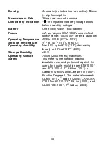
Page 30: ...Sensor Requires type K thermocouple Input Impedance 10M VDC 9M VAC AC Response True rms AC True RMS The term stands for Root Mean Square which represents the method of calculation of the voltage or c...

Page 31: ...to 40 C Storage Temperature 4 o F to 140 o F 20 o C to 60 o C Operating Humidity Max 80 up to 87 F 31 C decreasing linearly to 50 at 104 F 40 C Storage Humidity 80 Operating Altitude 7000ft 2000meters...

Page 32: ...31...

Reviews: