background image

24 

http://www.end.de 

DG - 10/2019

Mounting / Disassembly

5.5 

Connection of the pilot medium

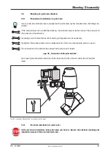
 You have to screw a appropriate hose connector into the pilot port.

By using liquid sealing compounds take care that no surplus sealing compound will flow into the 

pilot cylinder.

Feeds the pilot hose with pressure after the time will has gone by the manufacturer prescribes to  

harden the sealing compound. 

Connect the pilot medium hose with the hose connector. Use only the correct hose for your appli-

cation.

Fasten the hose into the hose connector.

By laying the hose take care, that the hose will not be creased, squezzed or sheared or that the 

hose will be layed over edges. Also take care that there will be no pressure or traction on the 

hose.

Lay the hoses to their starting positions as appropriate, in conduits or cable ducts.

Check the tightness af all connections.

Fig. 5.4 - mounting /disassembly - connection of the pilot medium

sealing compund 

harden

Summary of Contents for DF3D

Page 1: ...ynhausen Telefon 05731 7900 0 Telefax 05731 7900 199 http www end de Original Operating Manual Pressure Actuated Valves DG2D DA2D DL2D DM2D DF2D DFZ DG3D DA3D DL3D DM3D DF3D AX version acc to European Directve 2014 34 EU ATEX for the use in explosive atmosphere ...

Page 2: ...hout prior or direct notice to the client The contents of this publication are subject to change without notice This publication has been written with great care However END Armaturen GmbH Co KG cannot be held responsible either for any errors occurirng in this publication or for their consequences The products are specified by the statements in this documentation no assurance of the properties is...

Page 3: ... flow direction 16 4 5 1 4 Double acting 16 4 5 2 Description of function Pressure actuated valve 3 2 way 17 4 5 2 1 Split function 17 4 5 2 2 Mixing function 17 4 6 Description of options function 18 4 6 1 Pilot valve Option 18 4 6 2 Position indicator Option 18 4 6 3 Optical position indicator Option 18 4 6 4 Stroke stop Option 18 4 6 5 Electrical position indicator Option 18 4 6 6 Manual overri...

Page 4: ... valve 25 5 7 Disassembly 26 5 7 1 Mechanical disassembly 26 6 Starting 27 7 Failure 27 7 1 Failure causes 27 8 Maintenance Cleaning 28 8 1 Maintenance 28 8 2 Cleaning 28 9 Declaration of conformity 29 10 Annex 30 10 1 Conditions in the potentially explosive area 30 10 2 Equipment groups acc to EC directive 2014 34 EU Annex I 30 ...

Page 5: ...elative to pilot pressure and pressure range operations material connection type and connection size There are also several options available With accessories it can switch the pilot media it can indicate the position of the piston it can happen a manual override it can stop the stroke The field of use of this valve is predominantly in food and drink industry in chemical installtions in ventilatio...

Page 6: ...tion in the conditions of our delivery are partly completed machinery according to annex 2 paragraph g of the directive 2006 42 EC on machinery which must not be put into service until the final machinery into which it is to be incorporated has been declared in conformity with the provisions of the Directive 2006 42 EC on machinery where appropriate Please take notice to the Declaration of incorpo...

Page 7: ... period in accordance with the sales contract The end of the normal duration of live of the wearing parts represents no defect The warrently and guarantee rules of END Armaturen GmbH Co KG are applicable 2 5 Symbols and their signfication Paragraphs which are identified with this symbol contain very important advices this also includes advices for averting health risks Oserve these paragraphs with...

Page 8: ... trained specialist personnel having mechanical and electrical knowledge Switch off all the devices machines plant affected by mounting or repair If appropriate isolate the devices machines plant from the mains Check for example in chemical plants whether the switching off of devices machines plant will cause potential danger If appropriate in the event of a fault in the valve in a plant which is ...

Page 9: ...correct function and the tightness of the valve Check the right position and correct function of mounted pilot valves and limit switches Through suitable measures prevent actuating links being trapped by moving actuating ele ments Check the right function of all saftey devices for example emergency off push buttons safety valves etc Carry out the starting and the adjustments only in accordance wit...

Page 10: ...orresponding to its construction The valves must be used within the values specified in the technical data Satisfy yourself that as the result of the mounting the starting or as a result of the test adjusments on the valves no potential hazards will be produced for devices machines plant Open the valve only to such an extant as described in this documentation Do not loose the locking ring of the p...

Page 11: ...ription 4 1 Device description 1 Valve body 2 Pilot cylinder 3 Screw joint 4 Cap 5 Connection 6 Pilot port 7 Flow direction indicator 8 Name plate 9 Warning note 10 Connection for grounding Fig 4 1 Device descriptions front rear 6 2 3 1 5 7 8 9 4 5 10 Arma turen PE ...

Page 12: ...FE 6 NBR NBR 7 FKM FKM 8 FKM PTFE brass cylinder 0 Ø 32 mm 1 Ø 50 mm 2 Ø 80 mm 3 Ø 125 mm aluminium alloy 4 Ø 100 mm stainless steel cylinder 5 Ø 50 mm 6 Ø 80 mm 7 Ø 125 mm aluminium alloy 8 Ø 100 mm 9 Ø 32 mm threaded flanged and welded connection connection 006 G 008 G 010 G 015 G DN 15 020 G DN 20 025 G 1 DN 25 032 G 1 DN 32 040 G 1 DN 40 050 G 2 DN 50 065 G 2 DN 65 080 G 3 DN 80 100 G 4 DN 100...

Page 13: ...of the valve bar Steuerdruck Recommend pilot pressure of the valve bar Temperatur TS Temperature range of the valve Größe DN Connecting size of the valve Prüfdruck PT Testing pressure of the valve Fluidgruppe Allowed fluid group of the valve Herstellung Date of manufacturing II 2G Ex h IIC T4 Gb explosion proofed identification II 2D Ex h IIIC T135 Db END Armaturen GmbH Co KG D 32547 Bad Oeynhause...

Page 14: ...e actuated valve Group II Category 2G 2D for zone 1 and zone 21 Explosion proof classification h constructional safety Temperature class max temperature of the surface T4 Tmax 135 C T5 Tmax 100 C T6 Tmax 85 C 4 5 Corresponding use Pressure actuated valves are work equipment with constructional safety designed for applicati ons in atmospheres according to category 2G zone 1 zone 2 2D zone 21 zone 2...

Page 15: ... Because the valve closes with the flow direction the nominal pressure supports the closing pro cess and seals the valve disk against the seat additionally If the media flows through the valve with a high speed the valve could close to fast and this could causes pressure shocks in the pipes The electrical control signal will be changed into the pressure media control by an optional avai lable sole...

Page 16: ...ally close against the flow direction The in neutral position closed valve obtains this function by a spring which acts in close direction By feeding with compressed air the pilot pressure moves the piston against the spring and lift up the valve disk from the seat Therefore the valves open The valve closes against the flow direction only by the spring force Therefore the valve closes slowly and p...

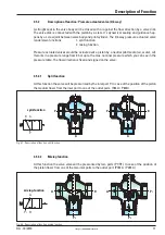
Page 17: ... by a stem It s dynamical sealing and guidance hap pens by a screw joint between valve body and pilot cylinder The 3 2 way pressure actuated valve renders two functions 1 split function 2 mixing function Pressure actuated valves would be actuated wit a piston by a neutral pilot media air water oil It works in a pressure range from 0 bar up to the max nominal pressure which you can see in the press...

Page 18: ...hich indicates the position of the valve on top of the pilot cylinder The hole for the red pin in the pilot cylinder is covered by a clear plastic cap You can see the pin in the position open 4 6 4 Stroke stop Option You are able to limited the stroke in the valve by a stroke stop Therefore you can regulate the flow rate of the valve 4 6 5 Electrical position indicator Option The electrical posito...

Page 19: ...t per sonnel having mechanical and electrical knowledge The following figures are showing the pressure actuated valves without any options Perhaps the valve mounting by you is equiped with option Your device variant you can see at the name plate on the pilot cylinder of the valve For their meaning see also chapter 4 2 Name plate The mechanical installation are the same by all variants It differs o...

Page 20: ...g on the place and the position of the point of weld Welding the parts at a serviceable device machine plant the potential of danger is as higher as welding the parts in a welding room If appropriate inform the shift foreman safety engineer or the works manager and the fire brigade of your factory By welding observe your own national guide lines about safety and prevention of accidents By welding ...

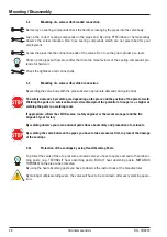
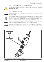
Page 21: ...e variants Therefore you have to screw a appropriate hose con nector into the pilot port and to connect it with a compressed air hose By feeding the hose with compressed air with a maximum pressure of 6 bar the valve disk will lift up from the seat Loosen the valve top with a fit spanner The spanner have to put on to the hexagon nut of the screw joint Never put the spanner on to the hexagon nut of...

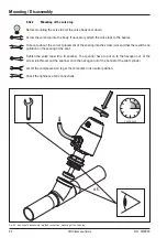
Page 22: ...sary attach the valve tops to the bodies Take care about the correct placement of the sealing into the screw joint and that there will be no pollution on the sealing or the seat Tighten the valve top with a fit spanner The spanner have to put on to the hexagon nut of the screw joint Never put the spanner on to the hexagon nut of the bonnet of the pilot cylinder Let off the compressed air to get th...

Page 23: ...valve body between the flanges by using the appropriate sealings Aligns the flange borings and put the fit screws through the holes Screw the fit nuts onto the screws and tighten it up crosswise By doing this observe the maximum torque moment of the screws Check the tightness af all connections Mounting Disassembly Fig 5 3 Mounting disassembly flanged connection flow direction o k cool down ...

Page 24: ...den the sealing compound Connect the pilot medium hose with the hose connector Use only the correct hose for your appli cation Fasten the hose into the hose connector By laying the hose take care that the hose will not be creased squezzed or sheared or that the hose will be layed over edges Also take care that there will be no pressure or traction on the hose Lay the hoses to their starting positi...

Page 25: ... male thread other sealing compounds are not necessary By tighten the solenoid valve use a suitabel spanner Don t use the solenoid valve as a lever The connection of the pilot media ensues by the devices of chapter 5 5 Connection of the pilot medium by screwing the threaded connection of the hose into the free thread connection of the pilot valve Fig 5 5 mounting disassembly mounting of a pilot va...

Page 26: ...ent starting up of the devices machines plants or the switching on of the pilot media supply or the switching on of the medium Keep ready some fit tanks to catch up leaking liquids 5 7 1 Mechanical disassembly Switch of the pilot media release the pressure in the pipes and take care to prevent the inad vertent switchnig on Loosen the fitting of the pilot medium and take away the pipe of the pilot ...

Page 27: ...e should occur please observe also Safety advice If necessary inform the shift foreman safety engineer or the manager about the disturbance without delay in order for example to avoid an outflow overflow of chemicals or a discharge of gases in good time by means of suitable measures Next using the following list 7 1 Failure causes attempt to find the reason for the causes of the failure and if it ...

Page 28: ...cation take care that there will only be used silicon free grease and slip agents In case of a defect in the pressure actuated valve make contact to the supplier The telephone number will be found on the back cover of these mounting and installation manual If you determinate that there is a demage to the pressure actuated valve isolate it from the supply lines However before you doing this it is e...

Page 29: ...3 Satety of machinery EN 60204 1 2014 10 Electrical equipment of machinery DIN EN ISO 80079 36 2016 12 Non electrical equipment for potentially explosive atmospheres Basic methods and requirements DIN EN ISO 80079 37 2016 12 Non electrical equipment for potentially explosive atmospheres Constructional safety C EN 1127 1 2011 10 Explosion Protection END Armaturen GmbH Co KG Oberbecksener Str 78 D 3...

Page 30: ...xplosive atmosphreres are likely to occur Equipment with normal safety level This means equipment of category 3 is intended for use in areas in which explosive atmospheres are unlikely to occur or if they do occur are likely to do so only infrequently and for a short period only 1G 1D 1D od 2D 1G od 2G 1D 2D 3D 1G 2G 3G Flammbable material Temporary behaviour of the flammable mate rial in the pote...

Page 31: ...DG 10 2019 http www end de 31 Notes ...

Page 32: ...sener Str 78 D 32547 Bad Oeynhausen Telefon 49 0 5731 7900 0 Telefax 49 0 5731 7900 199 Internet http www end de E Mail post end de Watergates GmbH Co KG Oberbecksener Str 70 D 32547 Bad Oeynhausen Telefon 49 0 5731 7900 0 Telefax 49 0 5731 7900 199 Internet http www watergates de E Mail post watergates de ...

Reviews: