


DEVICE DESCRIPTION
smart Econ - emz-HCW - 180116
15
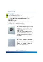
Connections and interfaces on the smart Econ HCW
The smart Econ HCW has the following connections inside the housing:
• Connections for pumps and mixers (terminal strips)
• Connections for temperature sensors (terminal strips)
• 1 CAN bus interface (terminal strip for 4-wire cable)
• 1 Ethernet interface (LAN) at the back of the housing (Western socket for CAT 5 cable)
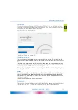
An Internet connection can be established via the LAN interface. This allows additional PC opera-
tion via the smart Econ Cloud (access optional).
“Internet-based network” on page 55
• 1 USB interface inside the housing (Micro-USB-B)
“Installation and connection” on page 45
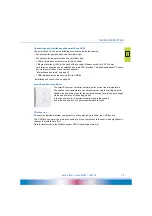
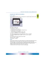
smart Econ Room controller
The smart Econ room controller determines the current room temperature.
The desired room temperature can be readjusted using the setting wheel.In
addition, the operating mode for the assigned heating circuits can be changed
via the end positions of the setting wheel:
In the end position (
+
) a permanent party mode (always heat)
and in the end position (
-
) a permanent setback function.
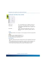
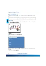
CAN bus line
Connect the individual system components in series with a 4-pole cable, the CAN bus line.
The CAN bus line merely has to be connected from one component to the next, which significantly
reduces the installation effort.
Data is transferred via the fieldbus system CAN (Control Area Network).


