13 – 2
Vission 20/20 • Operation and Service Manual •Vilter/Emerson • 35391SC 2.0
Section 13
•
Instruments Calibration
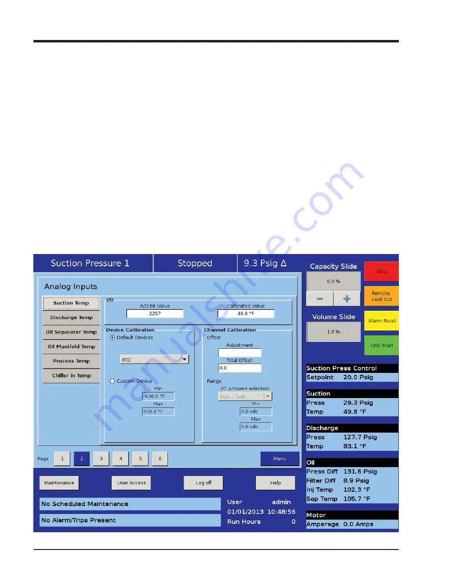
Custom Device:
• This option allows the operator to choose the mini-
mum and maximum value of the instrument being
used.
Offset:
• Once the two point calibration is completed, it is not
uncommon for there to be a small error. By entering
the value of the error from the calibrated value and
the actual value into the adjustment entry box, that
error will be added/subtracted from the total offset.
The offset is applied to the calibrated value which
should correct the error.
Range:
• This option is available when the custom device op-
tion is chosen. Here the operator de
fi
nes the signal
type and range transmitted by the instrument. The
operator can choose from several prede
fi
ned ranges
in the drop-down box or enter a value.
Motor Current
The Vission 20/20 has two options for measuring motor
current. A 4-20mA signal transmitted from an external
device or a 0-5Amp AC current Transformer. The type
of device being used is selected in the Con
fi
guration
Screen, Motor Current Device in Section 19.
The motor current tab has the ability to calibrate both
measurement options through the 4-20mA scale and
current transformer ratio sections, see Figure 13-3.
Instruments Calibration Screen - Analog Inputs (Page 3).
However, the device type that is selected in the con
fi
gu-
ration screen will be the only section that will be avail-
able to the operator.
The calibration differs from all other calibration proce-
dures in that the motor current must be calibrated while
the compressor is running at close to full load amps as
much as possible. In addition, the operator will need to
enter a value into the “Enter Desired Value” entry box
that is equal to the measured value in amps by a calibrat-
ing measurement device. After entering the measured
Figure 13-2. Instruments Calibration Screen - Analog Inputs (Page 2)
Summary of Contents for Vission 20/20
Page 1: ...Vission 20 20 micro controller Operation and service manual Version 2 0 ...
Page 2: ......
Page 4: ......
Page 6: ......
Page 66: ...8 4 Blank Vission 20 20 Operation and Service Manual Vilter Emerson 35391SC 2 0 ...
Page 76: ...10 8 Blank Vission 20 20 Operation and Service Manual Vilter Emerson 35391SC 2 0 ...
Page 86: ...12 6 Blank Vission 20 20 Operation and Service Manual Vilter Emerson 35391SC 2 0 ...
Page 106: ...15 4 Blank Vission 20 20 Operation and Service Manual Vilter Emerson 35391SC 1 9 ...
Page 108: ...16 2 Blank Vission 20 20 Operation and Service Manual Vilter Emerson 35391SC 2 0 ...
Page 136: ...21 4 Blank Vission 20 20 Operation and Service Manual Vilter Emerson 35391SC 2 0 ...
Page 146: ...24 4 Blank Vission 20 20 Operation and Service Manual Vilter Emerson 35391SC 2 0 ...
Page 154: ...26 4 Blank Vission 20 20 Operation and Service Manual Vilter Emerson 35391SC 2 0 ...
Page 156: ...A 2 Blank Vission 20 20 Operation and Service Manual Vilter Emerson 35391SC 2 0 ...
Page 158: ...B 2 Blank Vission 20 20 Operation and Service Manual Vilter Emerson 35391SC 2 0 ...
Page 162: ...B 6 Blank Vission 20 20 Operation and Service Manual Vilter Emerson 35391SC 2 0 ...
Page 180: ...B 24 Blank Vission 20 20 Operation and Service Manual Vilter Emerson 35391SC 2 0 ...
Page 204: ...B 48 Blank Vission 20 20 Operation and Service Manual Vilter Emerson 35391SC 2 0 ...
Page 220: ...B 64 Blank Vission 20 20 Operation and Service Manual Vilter Emerson 35391SC 2 0 ...
Page 257: ......


