


Parameter
structure
Keypad and
display
Parameter
x.00
Parameter
description format
Advanced parameter
descriptions
Macros
Serial comms
protocol
Electronic
nameplate
Performance
RFC mode
368
Unidrive SP Advanced User Guide
www.controltechniques.com Issue Number: 10
6 Macros
6.1 Introduction
A macro is a simple and easy way of setting up the parameter routing in
a drive for a specific application. It brings specific parameters into the
programmable section of menu 0 for easy access and sets up internal
software routing to give the user I/O terminals the functions required for
the application.
Unidrive classic had several predefined macros available for the
following types of set up.
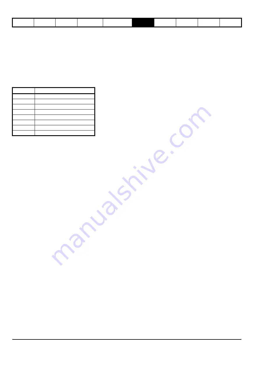
Table 6-1 Macros that are available
* Only available in closed loop vector or servo operating modes.
Macro 1 – Easy Mode
The Easy mode macro gives the simplest operation of the drive for basic
applications. It is identical to the default condition except that menu 0
has less parameters.
Macro 2 – Motorized potentiometer
The Motorized potentiometer macro enables the drive's own internal
motorized potentiometer to control the speed of the drive via digital
inputs. A digital input selects between an analog speed reference and
the motorized potentiometer reference.
Macro 3 – Preset frequencies / speeds
The Preset reference macro enables the use of preset references to
control the speed of the motor via digital inputs. A digital input selects
between an analog speed reference and the preset references.
Macro 4 – Torque control
The Torque control macro configures the drive for use in Torque control
mode, selectable via a digital input. Analog input 1 is configured for the
torque reference. When in speed control analog 2 is the speed
reference. When in torque control with the drive in closed loop mode
analog input 2 is the speed override reference. Enabling torque mode
with the drive in open loop mode will put the drive in to pure torque
control. In closed loop mode the drive will be put in to torque control with
speed override.
Macro 5 – PID (set-point control)
The PID control macro enables the drive's own internal PID controller to
control the speed of the motor. Analog input 1 is configured for the main
speed reference, analog input 2 is the PID reference and analog input 3
is the PID feedback. A digital input selects between an analog speed
reference and the PID control.
Macro 6 – Axis-limit control
The Axis limit control macro configures the drive for use with limit
switches so that the drive is stopped when a position limit has been
reached. The speed reference can be either unipolar or bipolar.
Macro 7 – Brake control
The brake control macro configures the drive to apply or release a
mechanical brake on a motor in a crane or hoist application. The drive
issues a brake release signal via a digital output when the relevant
conditions are met.
Macro 8 – Digital lock / shaft orientation
Only available in closed loop vector or servo operating modes.
Digital lock:
The drive operates as a slave in a closed loop master-slave system.
The slave motor is digitally locked to the master motor.
Shaft orientation:
The motor speed is controlled in the same way as for default operation,
but the motor shaft can be orientated to a specified angular position
before and/or after running the motor.
This section details how to replicate the Unidrive classic macros in a
Unidrive SP.
The programmable section of Menu 0 is from Pr
0.11
- Pr
0.30
inclusive.
The other menu 0 parameters have fixed functions used in every mode
as described below:
7
Macro
Description
1
Easy mode
2
Motorized potentiometer
3
Preset frequencies / speeds
4
Torque control
5
PID (set-point control)
6
Axis-limit control
7
Brake control
8*
Digital lock / shaft orientation
Summary of Contents for unidrive sp
Page 419: ......
Page 420: ...0471 0002 10 ...


