Emerson Scroll ZB*KAU Application Manuallines Download Page 21


© 2018 Emerson Climate Technologies, Inc.


21 

AE4-1431 R1 

In the case of an R290 compressor replacement the oil 
must  be  drained  out  of  the  compressor  and  the 
compressor  should  be  flushed  with  dry  nitrogen.

  DO 

NOT close the stubs with plugs.


In the case of a motor burnout, most of contaminated oil 
will be removed with the compressor. The rest of the oil 
is  cleaned  using  suction  and  liquid  line  filter  driers.  A 
100%  activated  alumina  suction  line  filter  drier  is 
recommended but it must be removed after 72 hours. 

6.3.2.  Start-up  of  a  new  or  replacement 

compressor 

Rapid  charging  only  on  the  suction  side  of  a  scroll-
equipped system can occasionally result in a temporary 
no-start  condition  for  the  compressor.  The  reason  for 
this is that, if the flanks of the scrolls happen to be in a 
sealed  position,  rapid  pressurization  of  the  low  side 
without  opposing  high-side  pressure  can  cause  the 
scrolls  to  seal  axially.  As  a  result,  until  the  pressures 
eventually  equalize,  the  scrolls  can  be  held  tightly 
together  preventing  rotation. 

The  charge  should  be 

done  on  the  high-pressure  side  of  the  system. 
Before  system  start-up,  allow  the  pressures  to 

equalize. 

Follow  instructions  detailed  about  tagging  and 
locking out on 

Safety Statements

 section on Pg. 5. 


Do  not  start  the  compressor  while  the  system  is  in  a 
deep vacuum. Internal arcing may occur when a Scroll 
compressor  is  started in  a  vacuum  causing  burnout  of 
the internal lead connections.  

6.3.3.  Compressor return procedure 

To  return  a  compressor  to  Emerson  for  analysis,  the 

procedure below shall be followed: 


During  the  entire  working  procedure  continuously 
check  if  the  ambient  atmosphere  is  explosive.  If 
explosive  atmosphere  is  detected  ensure  proper 
ventilation  of  the  working  space  and  immediately 
cut-off the power supply. 


Resume working after the atmosphere is no longer 
dangerous. 


Recover  the  refrigerant  from  the  system  using  a 

suitable recovery unit.  


Do  not  allow  the  recovery  unit  to  recover  below 
atmospheric pressure. Make sure the low-pressure 
switch  that  stops  the  recovery  process  is  not  set 
below 7 PSIG. 


At this pressure, some refrigerant will still be in the 
system.  Therefore,  before  opening  the  system, 
pressurize to 15 PSIG with dry nitrogen. 


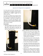
Open  the  system  with  a  cutting  tool  and  flush  the 
entire system with dry nitrogen. 


Disassemble  the  compressor  with  a  cutting  tool. 
Drain  and  recover  compressor  oil  properly.  Flush 
the compressor with dry nitrogen for a few minutes. 


The compressor should be returned free of oil and 
with  connections  open  -  do  not  close  connections 
with plugs. 


Properly  collect  and  secure  the  oil.  Provide 
information about the quantity of oil drained from the 
compressor  and  its  color.  Ideally,  send  a  good 
picture. 


Dispose  of  the  oil  according  to  local  rules  and 

regulations. 


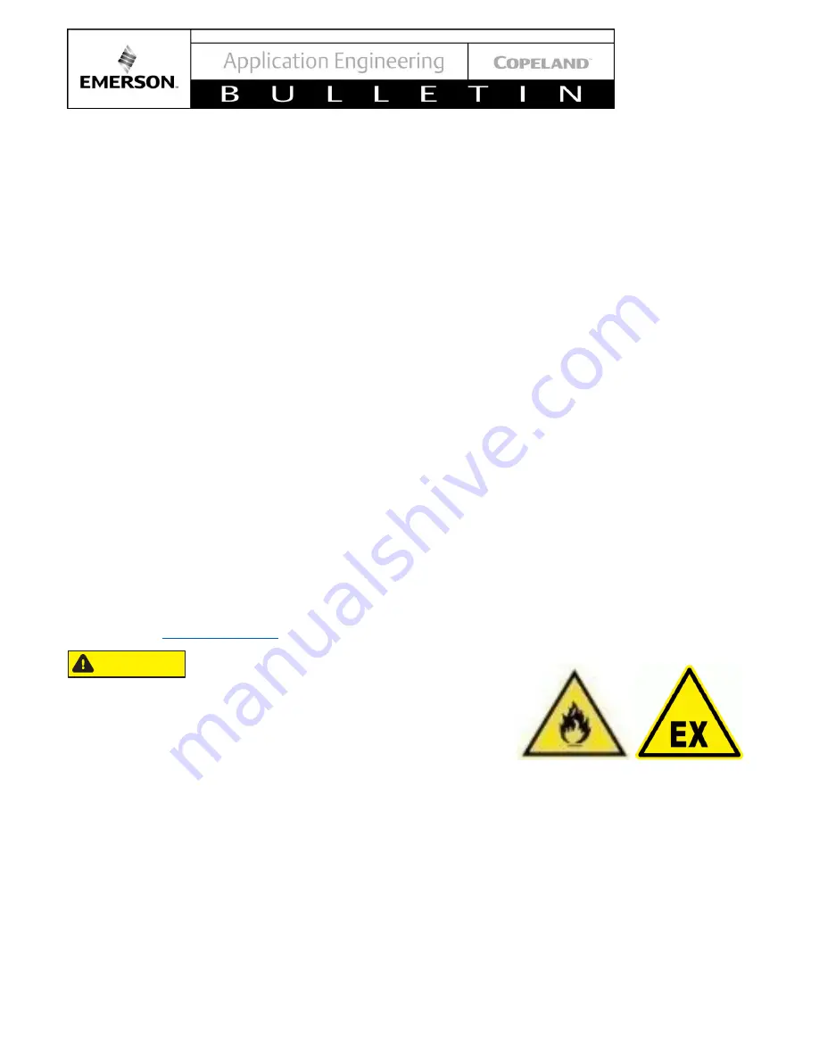
Use  a  proper  cardboard  box  package  when 
preparing  the  compressor  for  shipment.  Place 
warning  icons  on  each  side  and  on  the  top  of  the 
box: 


Mention  the  following  message  on  the  box: 

"Warning! 

Hydrocarbon 

compressor 

for 

analysis". 


The  compressor  shipment  must  be  kept  in  the 
upright position 

– mark it accordingly. 


If  more  than  one  compressor  is  returned,  each 
compressor has to be packed individually. 

NOTE:  Check  with  your  transport  company  to 
ensure compliance with all requirements for such a 
shipment. 


CAUTION


Summary of Contents for Scroll ZB*KAU

Page 1: ...its 12 4 2 3 Protection devices 14 4 2 4 Crankcase heaters 14 4 3 Pressure protection devices 14 4 3 1 High pressure protection 14 4 3 2 Low pressure protection 14 4 4 Discharge gas temperature protection 15 4 4 1 Excessive discharge gas temperatures 15 4 4 2 Discharge gas temperature protection 15 4 5 Motor protection 17 4 6 High potential testing 17 5 Starting up operation 17 5 1 Compressor tigh...

Page 2: ...tion USA 13 Figure 11 Terminal dome cover and correct electrical installation European Electrical 14 Figure 12 European Electrical connections 14 Figure 13 Cover European 14 Figure 14 ATEX discharge line thermostat and ATEX label 16 Figure 15 Suction tube connecting areas 20 Figure 16 Absorption of moisture in ester oil in comparison to mineral oil in ppm by weight at 77 F and 50 relative humidity...

Page 3: ...ese safety instructions Safety Icon Explanation DANGER indicates a hazardous situation which if not avoided will result in death or serious injury WARNING indicates a hazardous situation which if not avoided could result in death or serious injury CAUTION used with the safety alert symbol indicates a hazardous situation which if not avoided could result in minor or moderate injury NOTICE is used t...

Page 4: ...on oils Personal safety equipment must be used Failure to follow these warnings could result in serious personal injury BURN HAZARD Do not touch the compressor until it has cooled down Ensure that materials and wiring do not touch high temperature areas of the compressor Use caution when brazing system components Personal safety equipment must be used Failure to follow these warnings could result ...

Page 5: ...f a system never leave it unattended when it has no charge A servicing tag must be used for advising to other technician about servicing procedure running This will prevent unauthorized personnel from accidentally starting the equipment and potentially ruining the compressor by operating with no refrigerant In case of explosive atmosphere do not energize any electrical component in the system no u...

Page 6: ...r electrical component equipment no unshielded flame is allowed Furthermore before opening the refrigeration system or working on it with an unshielded flame continuously check if the ambient atmosphere is non explosive and ensure proper ventilation of the room before creating any naked flame no naked flame is allowed in an explosive atmosphere if the atmosphere reaches a dangerous concentration o...

Page 7: ...he relevant standards applicable to the given product Compressor Maximum Allowable Operation Pressure High pressure side Low pressure side ZB07KAU to ZB11KAU 406 PSIG 28 bar 247 PSIG 17 bar 2 2 3 Application limits Inadequate lubrication Compressor breakdown The superheat at the compressor suction inlet must always be sufficient to ensure that no refrigerant droplets enter the compressor For a typ...

Page 8: ...essor shell place a thermocouple on the bottom center not the side of the compressor shell and insulate from the ambient During rapid system changes such as defrost or ice harvest cycles this temperature difference may drop rapidly for a short period of time When the crankcase temperature difference falls below the recommended 50 F 27 K our recommendation is the duration should not exceed a maximu...

Page 9: ...escape Pulling the plugs in this sequence prevents oil mist from coating the suction tube making brazing difficult The copper coated steel suction tube should be cleaned before brazing The plugs must be removed as late as possible before brazing so that the air humidity does not affect the oil characteristics As oil might spill out of the suction connection located low on the shell the suction con...

Page 10: ...ame manner as any copper tube Recommended brazing material Any SIL FOS material is recommended preferably with a minimum of 5 silver However 0 silver is acceptable Be sure tube fitting inner diameter and tube outer diameter are clean prior to assembly Using a double tipped torch apply heat in area 1 As the tube approaches brazing temperature move the torch flame to area 2 Heat area 2 until braze t...

Page 11: ...el capacity and the condition pressure ratio 4 Electrical connection 4 1 Units Electrical connection per BOM 634 ZB KAU compressors for applications in US market are delivered with electrical pin connections ready for molded plug connection Its protection class is IP65 R290 qualified and dedicated molded plug cables must be used The R290 dedicated kit includes a special o ring a grounding connecti...

Page 12: ...electric current surge of the compressor motor at start up For more information please contact Application Engineering Figure 10 shows electrical connections schematic NOTE Emerson recommends the use of a Residual Current Device RCD as an additional safety measure NOTE Emerson recommends the use of a second contactor K2 for the safety chain of the compressor This protection must be considered it i...

Page 13: ...s they could damage the glass and or ceramic This might result in hermetic failure or loss of terminal performance Precautions are required to prevent striking or bending of pins Bent or damaged pins may result in loss of hermeticity and or terminal performance Power Circuit Control circuit Motor terminal connections Three phase compressors are connected to the TI T2 and T3 connections Legend B1 S...

Page 14: ...EC 60335 2 89 UL 60335 2 89 and EN 60335 2 89 no high pressure switch is required 4 3 2 Low pressure protection Operation under ambient pressure During operation under ambient pressure an explosive mixture can form inside the system Make sure that the pressure never falls below atmospheric pressure Operation outside the application envelope A low pressure protection shall be fitted in the suction ...

Page 15: ... ATEX directive consists of two EU directives describing what equipment and work space is allowed in an environment with an explosive atmosphere for 250 F 121 C for all ZB KAU models These compressors have no internal discharge gas temperature protection Therefore an external protector is required See Section 4 4 2 for more details 4 4 1 Excessive discharge gas temperatures A few of the possible c...

Page 16: ...the thermostat body against mechanical damage according to UL471 SB5 IEC 60079 0 clause 26 4 2 table 13 There is no need for an additional housing around the thermostat body Protection against mechanical damage to the thermostat can be achieved with an overall cover or box placed around the compressor or refrigerant system See Table 2 for Technical data of the discharge line thermostat For install...

Page 17: ... any remaining refrigerant from the compressor prior to high potential testing and Megohm resistance reading 5 Starting up operation 5 1 Compressor tightness test High pressure Personal injuries Consider personal safety requirements and refer to test pressures prior to test System explosion Personal injuries Use only dry nitrogen for leak testing DO NOT USE other industrial gases System contaminat...

Page 18: ...ill rotate in either direction depending on power phasing Since there is a 50 50 chance of connected power being backwards contractors should be warned of this Appropriate instructions or notices should be provided by the OEM Verification of proper rotation can be made by observing that the suction pressure drops and the discharge pressure rises when the compressor is energized There is no negativ...

Page 19: ...y case To maximize efficiency in controlling leaks when opening the refrigeration equipment or working on it it is recommended to use a leak detector designed for use with R290 refrigerant Continuously check if the ambient atmosphere is non explosive In case of explosive atmosphere do not energize any electrical component in the system fire and smoking are strictly forbidden no unshielded flame is...

Page 20: ...overy unit and dedicated cylinders Low suction pressure operation Compressor damage Do not operate with a restricted suction Do not operate with the low pressure limiter bridged Do not operate compressor at pressures that are not allowed by the operating envelope Allowing the suction pressure to drop below the envelope limit for more than a few seconds may overheat scrolls and cause early drive be...

Page 21: ... below shall be followed During the entire working procedure continuously check if the ambient atmosphere is explosive If explosive atmosphere is detected ensure proper ventilation of the working space and immediately cut off the power supply Resume working after the atmosphere is no longer dangerous Recover the refrigerant from the system using a suitable recovery unit Do not allow the recovery u...

Page 22: ...he actual moisture content of the lubricant samples must be taken from the system and analyzed 6 5 Oil additives Although Emerson cannot comment on any specific product from our own testing and experience we do not recommend the use of any additives to reduce compressor bearing losses or for any other purpose Furthermore the long term chemical stability of any additive in the presence of refrigera...

Page 23: ...val Dispose of oil and refrigerant according to national legislation and regulations Dispose of compressor according to national legislation and regulations 9 General Guidelines and More Information For general Copeland Scroll compressor please log in to Online Product Information at Emerson com OPI refer to the Application Engineering bulletins listed below or contact your Application Engineer 93...

Page 24: ...limate Technologies Inc and or its affiliates collectively Emerson as applicable reserve the right to modify the design or specifications of such products at any time without notice Emerson does not assume responsibility for the selection use or maintenance of any product Responsibility for proper selection use and maintenance of any Emerson product remains solely with the purchaser or end user Th...

Page 25: ...isture oxygen metal salts metal oxides and or high discharge temperatures The chemical reactions are accelerated at higher temperatures Oil and acid react with each other Acid formation leads to damage of the moving parts and in extreme cases to motor burnout Several different test methods can be used to test for acid formation If acid is present a complete oil change including the oil in the oil ...

Page 26: ...porator outlet is usually the consequence of oversized selection of the expansion valve or incorrect bulb sensor mounting The valve may freeze up in the open position due to accumulation of debris in the system For a system with very short refrigeration lines an accumulator is recommended Compressor operating outside the design limits Check the compressor suction and discharge pressures while it i...

Page 27: ... Try to limit the number of cycles to maximum 10 per hour Low gas velocity System gas velocity changes depending on temperature and load capacity control In low load conditions gas velocity may not be high enough to return oil to the compressor Low discharge pressure Low ambient temperature Fit a fan cycling control system Refrigerant undercharge Check the system for leaks Observe sight glass for ...

Page 28: ... can be measured from the top of the compressor footplate Figure 19 ZB KAU with external oil sight tube Figure 20 Markings on the external oil sight tube Start and run the system until it reaches stable conditions then run at stable conditions for a minimum of 15 minutes Stop the compressor and read the oil level during standstill Any oil level between 12oz 355 mL and 16oz 473 mL is in the nominal...

Page 29: ...of 50 F 27 C This crankcase differential temperature requirement supersedes the minimum suction superheat requirement detailed in section Applications limits To measure oil temperature through the compressor shell place a thermocouple on the bottom center not the side of the compressor shell and insulate from the ambient During rapid system changes such as defrost or ice harvest cycles this temper...

Reviews: