

© 2018 Emerson Climate Technologies, Inc.
12
AE4-1431 R1
4.1.2. Removing the molded plug power cable
•
Shut off power supply.
•
Remove the retainer from the connection.
•
Remove the molded plug connector from the
connection pins.
•
Disconnect the grounding from the compressor
circle fence.
Models with 634 BOM will be single and three phases.
For 3 phase units, pay special attention to appropriate
phase rotation to avoid reverse rotation of the scroll
motor.
4.2. Electrical installation
Conductor cables! Electrical shock!
Shut off power
supply before and between each test
The system capacitor may remain charged for a few
minutes after shutdown. Before starting to work on the
electrical installation make sure accidental sparking is
not possible.
Shut off power supply before and between each test.
Continuously check if the ambient atmosphere is non
explosive and ensure proper ventilation before and
when working on the electrical installation.
With flammable or explosive atmosphere no work on the
electrical installation is allowed. If the atmosphere
reaches a dangerous concentration of flammable gas
immediately stop any work on the electrical installation,
avoid any source of ignition and ensure proper
ventilation of the room.
4.2.1. US Units
A motor soft starter can also be used to temporarily
reduce the load, the torque and the electric current
surge of the compressor motor at start-up. For more
information please contact Application Engineering.
shows electrical connections schematic.
NOTE: Emerson recommends the use of a Residual
Current Device (RCD) as an additional safety measure.
NOTE: Emerson recommends the use of a second
contactor K2 for the safety chain of the compressor. This
protection must be considered it in conjunction with the
mentioned RCD.
4.2.2. European Units
4.2.2.1. European Units Electrical connections.
In EU compressors electrical connection is only
available using a terminal dome cover. Due to the IP11
certification of the terminal box, the compressor has to
be protected by a cover, which can only be opened with
a tool.
The compressor terminal box has a wiring diagram on
its cover. Before connecting the compressor, ensure the
supply voltage, the phases and the frequency match the
nameplate data.
When installing these compressors in the system, the
following steps must be taken:
•
Add the foam gasket and the plastic terminal cover.
•
To connect the power leads, use suitable 90°
insulated female crimp connector terminals from
"250 series" suitable for 0.250-inch (6.35 mm) male
tab width. See
•
To ensure the wires are properly terminated, the
correct terminal and clamping tool for the selected
wire size must be used.
•
The ground wiring must conform to local regulations
and codes of practice (only the provided parts must
be used).
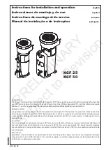
Figure 8 - Principle of connecting the molded
plug power cable to the connection pins
WARNING