Quick Start Guide
00825-0200-4840, Rev BB
July 2016
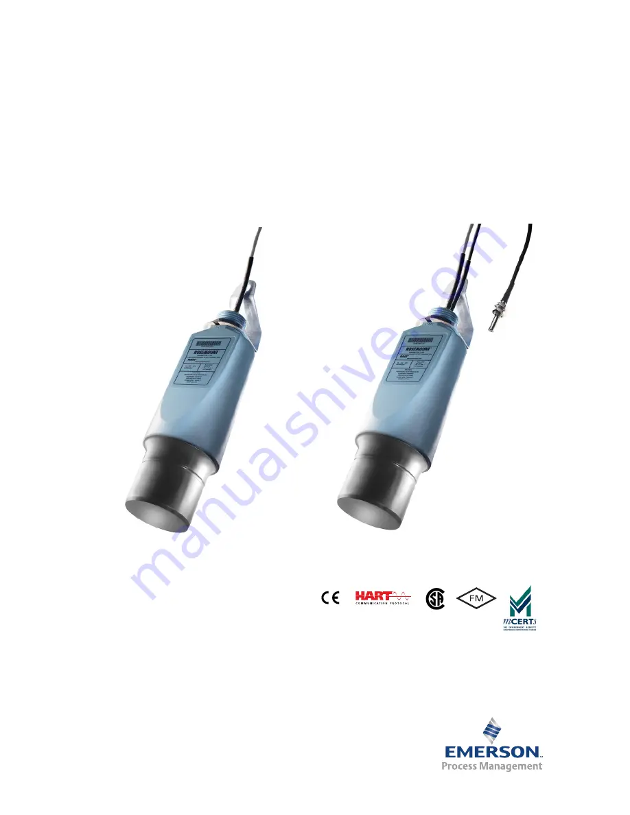
Rosemount Ultrasonic3107 Level and 3108 Flow Transmitters
Page 1: ...Quick Start Guide 00825 0200 4840 Rev BB July 2016 Rosemount Ultrasonic 3107 Level and 3108 Flow Transmitters ...
Page 2: ... hazardous environment must be in accordance with the appropriate local national and international standards codes and practices Please review the Product Certifications section for any restrictions associated with a safe installation Before connecting a Field Communicator in an explosive atmosphere ensure the instruments are installed in accordance with intrinsically safe or non incendive field w...
Page 3: ...ach transmitter is designed to be mounted above a liquid and uses ultrasonic pulses to continuously measure the distance to the liquid surface The microprocessor controlled electronics calculates distance to the liquid level from the time delay between the transmitting and receiving of signals When programmed with the bottom reference of the application usually the bottom of a tank the transmitter...
Page 4: ...ed in its construction e g shrouded from direct sunlight Note See also Product Certifications on page 21 for special conditions for safe use General Installation must be carried out by suitably trained personnel in accordance with the applicable code of practice If the equipment is likely to come into contact with aggressive substances it is the responsibility of the user to take suitable precauti...
Page 5: ...ed electrical device Environmental The Rosemount 3107 and 3108 ultrasonic transmitters are Intrinsically Safe IS approved for hazardous area installations The 3107 is designed for open or closed tank installation It is weatherproof and protected against the ingress of dust The 3108 is designed for open channel flow measurement It is weatherproof and protected against the ingress of dust Avoid inst...
Page 6: ...form on the transmitter face If the transmitter is mounted in a stand off or nozzle the transmitter face should protrude at least 0 2 in 5 mm into the tank If the transmitter is used in environments where direct sunlight can cause high surface temperatures on exposed instruments a sun shade is recommended Mounting the transmitter above the liquid surface A 1 in thread is provided to mount the tran...
Page 7: ...raised face mating flange on the tank or vessel to prevent distortion of the PVC flange by over tightening the bolts See Product Data Sheet for a list of all accessories and their part numbers Figure 5 Flange mounting A Transmitter is mounted vertically maximum deviation of 3 B 6 beam half angle C 1 3 in ft 11 cm m Minimum of 12 in 0 3 m Mounting from a conduit The 3107 and the 3108 can be mounted...
Page 8: ... optimum accuracy position the transmitter s front face at a height equal to the sum of the maximum flow depth plus the transmitter deadband of 12 2 in 300 mm plus an extra 2 in 50 mm It is important that the bottom reference of the transmitter should be related to the datum of the primary measuring device Figure 7 When setting the bottom reference on a V notch weir it is important the true invert...
Page 9: ...sunlight and solar radiation Enclosed or partially covered flume chamber Mount the remote temperature sensor in the approach channel in a shaded area away from direct sunlight and solar radiation The temperature sensor should be positioned in the weir chamber or flume approach channel so the average air temperature can be accurately measured The temperature sensor must be protected at all times fr...
Page 10: ...nded using a junction box and suitable extension cable Installation in a non hazardous area 1 Make sure that the power supply is disconnected 2 Connect the cable wires Figure 9 taking note of the required voltage of 12 to 40 Vdc for non hazardous applications Installation in a hazardous area When used with a Rosemount 3490 Series Control Unit no additional safety barriers are required If powering ...
Page 11: ...ctory settings in the appropriate units Field Communicator and AMS To view or change the transmitter base units 1 From the Home screen select 3 Service Tools 2 Select 4 Maintenance 3 Select 3 Utilities 4 Select 3 Set Base Units 5 Select new base units Note When on screen messages appear take action if needed and press OK Rosemount 3490 Series Control Unit To view or change the transmitter base uni...
Page 12: ...ing the transmitter Field Communicator or AMS To view or change the bottom reference 1 From the Home screen select 2 Configure 2 Select 2 Manual Setup 3 Select 1 Basic Setup 4 Select 2 Bottom Reference P010 5 Input the new bottom reference and press ENTER to save it 6 Press SEND to update the transmitter Rosemount 3490 Series Control Unit To view or change the bottom reference 1 From the Main Menu...
Page 13: ...and FV to a Host 2 2 1 3 SETUP Tag OUTPUT CURRENT Upper Range Val 4mA Point1 2 2 1 4 SETUP Tag OUTPUT CURRENT Lower Range Val Primary Variable D900 1 2 1 MONITOR Tag READINGS VARIABLES Primary Variable Level SV D901 1 2 2 MONITOR Tag READINGS VARIABLES Level SV Distance TV D902 3 2 1 3 MONITOR Tag READINGS VARIABLES Distance TV Distance D910 3 1 2 1 1 MONITOR Tag DIAGNOSTICS Distance Abbreviations...
Page 14: ...RT Master Device host Rosemount 3490 Series Control Unit To view or change the PV Units 1 From the Main Menu screen select SETUP 2 Select the transmitter e g Tx1 3107 3 Select UNITS and then select PV Units 4 Follow the on screen instructions to select and confirm the new setting If the HART PV has no units select and confirm the None option Transmitter tank shape non linear profile P011 This sele...
Page 15: ... 3 Note When on screen messages appear take action if needed and press OK Rosemount 3490 Series Control Unit To change the tank shape non linear profile 1 From the Main Menu screen select SETUP 2 Select the transmitter e g Tx1 3107 3 Select DUTY and then select Tank Shape 4 Follow the on screen instructions to select and save the new setting Select Non Linear Profile Linear Linear Special Plotted ...
Page 16: ... a volume measurement from an irregular shaped tank use this parameter to enter the maximum volume relating to the Profile Height page 17 See also the Special Plot section on page 19 for defining the irregular shaped tank Figure 11 Volume from a cylinder sphere A Rosemount 3107 or 3108 B Rosemount 3490 Series Control Unit C 4 20mA HART D Bottom Reference P010 E Profile Height P014 Open channel mea...
Page 17: ...t When the process value PV is a volume measurement from a standard non linear shaped tank e g an ideal horizontal cylinder or a sphere use this parameter to enter the diameter see Figure 11 on page 16 When the PV is a volume measurement from a regular shaped tank e g square or rectangular this parameter is not used When the PV is a volume measurement from an irregular shaped tank use this paramet...
Page 18: ...he diameter maximum height or power factor 1 From the Main Menu screen select SETUP 2 Select the transmitter e g Tx1 3107 3 Select DUTY 4 Select Profile Height 5 Follow the on screen instructions to edit and save the new setting Press the Enter key if prompted to change the mode to off line 6 Select Quit to exit to the previous menu Note Some flow profiles automatically populate this parameter and...
Page 19: ...Profile Pt 1 5 Follow the on screen instructions to edit and save the new setting Press the Enter key if prompted to change the mode to off line 6 Select Quit to exit to the previous menu Procedure for P011 Special Plot 1 Draw the graph of Process Value PV versus Liquid Height and note the maximum points Figure n 2 Enter the maximum volume or flow into PV Scale Factor P013 page 16 3 Enter the maxi...
Page 20: ...ile height P014 Bottom reference P010 Rosemount 3490 Series control unit Y X 0 0 P039 Maximum process value PV Maximum height P014 Entered percentages relating output PV to maximum PV Fixed percentages relating height to maximum height 10 20 30 40 50 60 70 80 90 100 P030 P031 P032 P033 P035 P036 P037 P038 P039 P034 P013 Maximum volume or flow ...
Page 21: ...ED Directive Electro magnetic compatibility EMC 2004 108 EC EN 61326 1 2006 MCERTS Certification 3108 only Sira Certificate No MC080131 Hazardous locations certificates Note Refer to the housing label to identify the approvals for your transmitter American and Canadian certifications Factory Mutual FM Approval I5 FM Intrinsically Safe Intrinsically Safe for Class I Division 1 Groups A B C and D Zo...
Page 22: ...y certificate number Sira 09ATEX2299X 1 The equipment may be used with flammable gases and vapors with apparatus groups IIA IIB and IIC and with temperature classes T1 T2 T3 T4 T5 and T6 2 Installation of this equipment shall be carried out by suitably trained personnel in accordance with the applicable code of practice 3 The equipment is not intended to be repaired by the user and is to be replac...
Page 23: ...IC Ga T6 Ta 40 to 55 C T4 Ta 40 to 60 C Ui 30V li 120mA Pi 0 82W Li 27μH Ci 5nF 8 Special conditions for safe use a The equipment must not be installed directly in any process where the enclosure might be charged by the rapid flow of non conductive media b The equipment must only be cleaned with a damp cloth c Do not mount the 3107 3108 on a structure that is subject to vibration or in a position ...
Page 24: ...July 2016 24 Quick Start Guide Figure 13 EC declaration of conformity certificate ...
Page 25: ...Quick Start Guide 25 July 2016 ...
Page 26: ...July 2016 26 Quick Start Guide ...
Page 27: ...bly X O O O O O ༣փ㓴Ԧ Housing Assembly O O O O O O Րᝏಘ㓴Ԧ Sensor Assembly X O O O O O ᵜ㺘Ṭ ᦞ SJ T11364Ⲵ㿴ᇊ㘼ࡦ This table is proposed in accordance with the provision of SJ T11364 O Ѫ䈕䜘ԦⲴᡰᴹ 䍘ᶀᯉѝ䈕ᴹᇣ 䍘Ⲵਜ਼䟿 վҾGB T 26572ᡰ㿴ᇊⲴ䲀䟿㾱 O Indicate that said hazardous substance in all of the homogeneous materials for this part is below the limit requirement of GB T 26572 X Ѫ 䈕䜘Ԧᡰ Ⲵᡰᴹ 䍘ᶀᯉ䟼ˈ㠣ቁᴹа 䍘ᶀᯉѝ䈕ᴹᇣ 䍘Ⲵਜ਼䟿儈ҾGB T 26572...
Page 28: ...ages Terms of Use aspx The Emerson logo is a trademark and service mark of Emerson Electric Co Rosemount and Rosemount logotype are trademarks of Emerson Process Management All other marks are the property of their respective owners Emerson Process Management All rights reserved GmbH Co OHG Emerson Process Management Argelsrieder Feld 3 82234 Wessling Germany 49 8153 9390 49 8153 939172 Asia Pacif...