background image

2.7

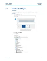
Establish the COM port

Prerequisites

When first connecting the harness, you will be prompted to select a COM port.

Procedure

1. Open Modbus

®

 Manager.

2. Select 

Device Manager

.

3. Select 

Ports

.

Reference Manual

Initial setup

00809-1500-4975

June 2021

Rosemount 975

11

Summary of Contents for Rosemount 975

Page 1: ...Reference Manual 00809 1500 4975 Rev AA June 2021 Rosemount 975 Flame Detectors Modbus Manager Manual ...

Page 2: ...that a the licensed firmware embodied in the Goods will execute the programming instructions provided by Seller b that the Goods manufactured by Seller will be free from defects in materials or workmanship under normal use and care and c Services will be performed by trained personnel using proper equipment and instrumentation for the particular Service provided The foregoing warranties will apply...

Page 3: ...CLUDE INCIDENTAL CONSEQUENTIAL OR PUNITIVE DAMAGES THE TERM CONSEQUENTIAL DAMAGES SHALL INCLUDE BUT NOT BE LIMITED TO LOSS OF ANTICIPATED PROFITS REVENUE OR USE AND COSTS INCURRED INCLUDING WITHOUT LIMITATION FOR CAPITAL FUEL AND POWER AND CLAIMS OF BUYER S CUSTOMERS Technical support To get technical support for this product contact your local Rosemount representative or the Rosemount Technical S...

Page 4: ...Abbreviation or acronym Definition UNC Unified coarse thread Vac Volts alternating current Vdc Volts direct current 4 ...

Page 5: ...ssign address to device 16 3 4 Switch device address 16 3 5 Locating the detector address 17 3 6 Status screen 17 3 7 Trend screen 18 3 8 Recording screen 19 3 9 Detector setup 21 Chapter 4 Maintenance 27 4 1 Miscellaneous functions 27 4 2 Update firmware 27 4 3 Parameter update 27 4 4 Set fixed current 4 20 values 28 4 5 Parameter download 29 4 6 Version information 29 4 7 Service functions 29 Ap...

Page 6: ...Contents Reference Manual June 2021 00809 1500 4975 6 Emerson com ...

Page 7: ...instructions on how to install operate and maintain the software Note The Modbus Manager software is for use with Rosemount 975 models only 1 2 Minimum requirements The minimum requirements for operating the Modbus Manager are as follows Pentium 3GHz Microsoft Windows XP 7 8 or 10 2GB RAM 10GB hard disk free space Isolated RS 485 interface card to be defined as COM or an RS 485 converter to connec...

Page 8: ...Introduction Reference Manual June 2021 00809 1500 4975 8 Emerson com ...

Page 9: ...er place it in a convenient location To run the software double click on the executable file 2 3 Connect computer to the device Prerequisites The computer must first be connected to the device using the RS485 harness cable before performing any configuration or diagnostic operations on the device Procedure 1 Connect one end of the USB cable to the computer USB port 2 Connect the other end of the U...

Page 10: ...ct RS 485 to Pin 1 3 Connect RTN to Pin 5 2 6 Set up USB adapter CAUTION If using a different adapter than recommended check that the D connector adapter wiring is similar to the wiring shown if not adjust the cable wiring to fit the desired adapter Procedure 1 Unscrew the cover of the USB adapter 2 Set up jumpers using one of the following options 3 Close the USB adapter cover 4 Connect the cable...

Page 11: ...requisites When first connecting the harness you will be prompted to select a COM port Procedure 1 Open Modbus Manager 2 Select Device Manager 3 Select Ports Reference Manual Initial setup 00809 1500 4975 June 2021 Rosemount 975 11 ...

Page 12: ...nager must be restarted 2 8 Connecting the device The device must be connected to power and the RS485 should be connected to the terminals according to the following table Function Wire color Terminal RS485 Red 13 RS485 Black 14 Note The detector address set by the factory is 1 When locating the detector address only one detector should be connected Initial setup Reference Manual June 2021 00809 1...

Page 13: ...very screen The left menu displays the brand name and navigation controls the top menu displays device information A Device brand B Top menu device information C Left menu navigation controls D Settings and actions Reference Manual Operation 00809 1500 4975 June 2021 Rosemount 975 13 ...

Page 14: ...al number C Full detector model code D Communication status E Detector status F Analog output signal G Heater status H Relay status green indicates de energized state for alarm and ACC energized for fault red indicates energized state for alarm and ACC de energized for fault Operation Reference Manual June 2021 00809 1500 4975 14 Emerson com ...

Page 15: ...le A Device information B Device status C Device setup D Device and software version 3 2 Perform manual BIT Procedure Click the Built In Test BIT button Performing BIT sets field of view If the detector is not mounted in its final position BIT will need to be performed again Reference Manual Operation 00809 1500 4975 June 2021 Rosemount 975 15 ...

Page 16: ...the Set New button 3 4 Switch device address Procedure 1 In the Address pane select the Switch to Detector radio button 2 Use the Address dropdown to select the required address 3 Click the Switch button Note Alternatively the up and down arrows can be used to switch the address without clicking the Switch button Operation Reference Manual June 2021 00809 1500 4975 16 Emerson com ...

Page 17: ...s address can be located by clicking the Locate button within the Locate Detector Address pane Once communication is established the current detector address will be shown in the top menu 3 6 Status screen This screen displays the device status Reference Manual Operation 00809 1500 4975 June 2021 Rosemount 975 17 ...

Page 18: ...lected unit C Shows current 4 20 analog output in mA D Activates manual BIT 3 7 Trend screen This screen shows the input voltage internal temperature and analog output live trends according to the selected timeframe Operation Reference Manual June 2021 00809 1500 4975 18 Emerson com ...

Page 19: ...can be adjusted by selecting the required values and clicking the Reset button 3 8 Recording screen This screen allows data from detector currently connected to be recorded and exported into a txt or xls file 3 8 1 Record data Procedure 1 Select the required recording mode Reference Manual Operation 00809 1500 4975 June 2021 Rosemount 975 19 ...

Page 20: ...on is in the Modbus directory installed on the computer in a file entitled Recordings Rosemount 975 MR and HR file names are QuadIRlog_YMDHMS Year Month Date Hours Minute Second Rosemount 975 UF and UR file names are prefaced with UVIRlog_YMDHMS Year Month Date Hours Minute Second The time stamp is according to GMT 3 8 2 View internal log The log displays the 12 most recent records without scrolli...

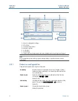
Page 21: ... Get button G Opens selected number of most recent records in txt format 3 9 Detector setup The detector is setup using the Detector Setup screen in which configurable options BIT settings Accessory Relay Options Detection Options Lock Option and 4 20 Settings can be changed Note 4 20mA settings for fault mode the default indication is 1mA but may be changed to 0mA To preserve the HART communicati...

Page 22: ...rameters may be configured Sensitivity Sets the detector s sensitivity in meters A higher number indicates greater sensitivity See relevant product manual for more information Heater mode Demister settings for clearing condensation from the lens Choose from On Off or Auto Default Auto Alarm delay The delay between detection of a signal and activation of the alarm Choose from 0 3 5 10 20 30 or A an...

Page 23: ...ay on successful manual BIT Activates the accessory relay when a manual BIT is successfully completed Default Not enabled Post manual BIT indication duration in seconds Enables the user to configure the alarm duration maximum 60 after successful manual BIT Default 3 3 9 3 Accessory relay options These options may be changed as described Activate accessory relay on warning When the detector s statu...

Page 24: ...vious password contact the manufacturer to receive a time limited password to reset the password Once received use the Enable Password reset button in the Version Service menu When the locked option is selected access to selected actions is controlled There are two independent permission types that allow access to the actions listed in Table 3 1 once the detector is locked by passwords When select...

Page 25: ...rning 3 5mA should always be the normal value Default 4mA Normal 4 or 5mA should always be the FOV value Default 4mA Pre alarm warning 13 16mA should always be lower than alarm value Default 16mA Alarm 15 20mA should always be higher than warning Default 20mA Once values are entered click the OK button to save the changes 3 9 7 Modbus Manager settings The Modbus Manager Settings screen is used to ...

Page 26: ...Note The application must be restarted for changes to take effect Operation Reference Manual June 2021 00809 1500 4975 26 Emerson com ...

Page 27: ...parameters file 4 2 Update firmware Prerequisites Firmware update file will be provided Procedure 1 Save file to your computer 2 Switch to the required baud rate 3 Click the Firmware update button 4 Follow on screen instructions to complete the process 4 3 Parameter update There is an optional feature to upload device parameters file with extension upm Reference Manual Maintenance 00809 1500 4975 ...

Page 28: ...ng can be adjusted within 0 05mA Procedure 1 Select the 4 mA radio button 2 Click Set fixed current 3 Enter multimeter reading 4 Click the Apply button 5 Repeat steps Step 3 and Step 4 until you enter value within 4mA 0 5 Important It is essential to enter the final value and click Apply 6 Select the 20 mA radio button 7 Click Set fixed current 8 Enter multimeter reading 9 Click the Apply button 1...

Page 29: ... the subfolder with the detector serial number included in the title Where required this file will be provided by the manufacturer 4 6 Version information Detector information and the software version can be viewed on this screen 4 7 Service functions This screen provides access to various service functions Reference Manual Maintenance 00809 1500 4975 June 2021 Rosemount 975 29 ...

Page 30: ...ne time password received from the manufacturer to enter tech mode B Enter one time password received from the manufacturer to reset password Maintenance Reference Manual June 2021 00809 1500 4975 30 Emerson com ...

Page 31: ...view current Rosemount 975 Series product certifications and installation drawings follow these steps Procedure 1 Go to Emerson com en us catalog flame detectors 2 Select the appropriate product 3 Scroll down to Documents and Drawings 4 Select CERTIFICATES APPROVALS 5 Select the appropriate document A 3 Failure status codes Rosemount 975 MR and HR Models Status Description 4 20mA output Analog out...

Page 32: ...burning P74 RAM CRC failure 1mA 0v Open 4Hz blinking orange Every 30msec P75 None of the parameters exist 1mA 0v Open 4Hz blinking orange At start up P76 RAM parameters CRC failure 1mA 0v Open 4Hz blinking orange Every hour F31 Sensor 4 5µ circuit failure no signal 1mA 0v Open 4Hz blinking orange Auto manual BIT F32 Sensor 5µ circuit failure no signal 1mA 0v Open 4Hz blinking orange Auto manual BI...

Page 33: ...oise 1mA 0v Open 4Hz blinking orange Every 30msec F55 Sensor 4 5 and 5 short circuit 1mA 0v Open 4Hz blinking orange Every BIT F56 Sensor 4 5 and 4 short circuit 1mA 0v Open 4Hz blinking orange Every BIT F57 Sensor 4 and 5 short circuit 1mA 0v Open 4Hz blinking orange Every BIT F58 Sensor 4 4 and 4 55 short circuit 1mA 0v Open 4Hz blinking orange Every BIT F59 Sensor 4 4 and 4 short circuit 1mA 0v...

Page 34: ...lose 4Hz blinking orange Every 30msec N8 BIT failure 2mA 0v Open 4Hz blinking orange Every BIT N9 Damaged BIT lamp 2mA 0v Open 4Hz blinking orange Every BIT N11 FOV failure 4mA 2v Close 1Hz blinking green Every 30msec N12 Missed ADC reading 4mA 2v Close 1Hz blinking green Every 30msec N13 Analog output failure 4mA 0v Close 4Hz blinking orange Every 30msec N18 FOV warning 4mA 2v Close 1Hz blinking ...

Page 35: ... The detector turns to V81 V82 after two minutes 2 The detector turns to V83 after 50 seconds 3 Unless in Setup table define constant red 4 4mA if from state N 16mA if from state T Rosemount 975 UF and UR Models Status Description 4 20mA output Analog output Fault relay LED indicator Test rate S90 Start up 1mA 0v Open 4Hz blinking orange Every start up S91 E2PROM parameter restoration 1mA 0v Open ...

Page 36: ...e 1mA 0v Open 4Hz blinking orange Every hour F38 Wrong AFE offset 1mA 0v Open 4Hz blinking orange Every 30msec F41 Constant UV 1mA 0v Open 4Hz blinking orange Every 30msec F42 Noisy UV 1mA 0v Open 4Hz blinking orange Every 30msec F43 UV high voltage failure 1mA 0v Open 4Hz blinking orange Every 30msec F44 IR sensor failure no signal 1mA 0v Open 4Hz blinking orange Auto manual BIT F45 IR circuit sh...

Page 37: ... N1 Constant external BIT 4mA 2v Close 4Hz blinking orange Every 30msec N2 Wrong ambient temperature 4mA 2v Close 4Hz blinking orange Every 30msec N3 4 20mA circuit failure 0 mA 2v Close 4Hz blinking orange Every 30msec N4 Fault relay failure 4mA 2v Open 4Hz blinking orange Every 30msec N5 Accessory relay failure 4mA 2v Open 4Hz blinking orange Every 30msec N6 Alarm relay failure 4mA 2v Open 4Hz b...

Page 38: ... UV level 12mA 2v Close 1Hz blinking green Every 30msec B0 IR UV automatic BIT 4mA 2v Close 1Hz blinking green Every IR BIT M0 IR UV manual BIT 4mA 2v Close 1Hz blinking green 3 Every IR BIT E0 IR UV end of BIT 4mA 2v Close 1Hz blinking green 3 Every IR BIT G0 Temperature gradient 4mA 2v Close 1Hz blinking green Every 30msec T0 Alarm delay 16mA 2v Close 2Hz blinking red Every 30msec W0 Warning 16m...

Page 39: ...nalog output Fault relay LED indicator Test rate J0 Anti flare 4 2v Close 1Hz blinking green Every 30msec X0 Explosion 20mA 5v Close Constant red Every 0 23msec Reference Manual Reference data 00809 1500 4975 June 2021 Rosemount 975 39 ...

Page 40: ... All rights reserved Emerson Terms and Conditions of Sale are available upon request The Emerson logo is a trademark and service mark of Emerson Electric Co Rosemount is a mark of one of the Emerson family of companies All other marks are the property of their respective owners ...

Reviews: