background image

4

Configuration

4.1

Adjustment of the signal output

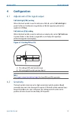
Fail Safe High (FSH) setting

When the level switch is used to indicate a full-silo, set to 

Fail Safe High

. A

power failure or line break is regarded as a full-silo signal (as protection
against overfilling).

Fail Safe Low (FSL) setting

When the level switch is used to indicate an empty-silo, set to 

Fail Safe Low

.

A power failure or line break is regarded as an empty-silo signal (as
protection against running dry).

Figure 4-1: Setting FSH or FSL

B

A

A. FSL setting (DIP-switch position up)

B. FSH setting (DIP-switch position down)

Note

See 

Signal output (switching logic)

 for how FSH and FSL operates.

4.2

Sensitivity

The level switch is factory-set to high sensitivity (switch position 

B

)and

normally does not to be changed. However, if the bulk solids material has a
frequent tendency to cake or deposit, the setting switch can be set to
position 

A

 to decrease the sensitivity of the probe.

October 2019

Quick Start Guide

Quick Start Guide

19

Summary of Contents for Rosemount 2511

Page 1: ...Quick Start Guide 00825 0100 2511 Rev AA October 2019 Rosemount 2511 Solids Level Switch Vibrating Fork ...

Page 2: ...Contents Introduction 3 Mechanical installation 8 Electrical installation 13 Configuration 19 Operation 21 Maintenance 22 Quick Start Guide October 2019 2 Quick Start Guide ...

Page 3: ...oting and order related questions United States 1 800 999 9307 7 00 am to 7 00 pm CST Asia Pacific 65 777 8211 North American Response Center Equipment service needs 1 800 654 7768 24 hours a day includes Canada Outside of these areas contact your local Emerson representative WARNING Physical access Unauthorized personnel may potentially cause significant damage to and or misconfiguration of end u...

Page 4: ...he level switch Ensure the wiring is suitable for the electrical current and the insulation is suitable for the voltage temperature and environment Process leaks could result in death or serious injury Ensure the level switch is handled carefully If the process seal is damaged gas or dust might escape from the silo or other vessel Any substitution of non recognized parts may jeopardize safety Repa...

Page 5: ...mount 2511 Solids Level Switch is used for monitoring the level of bulk materials in all types of containers and silos The level switch can be used with all powdery and granulated bulk materials that have a density greater than 30 g l 1 9 lb ft3 and that do not show a strong tendency to form crusts or deposits Typical applications are Building materials Lime extruded polystyrene foam XPS molding s...

Page 6: ...he level switch Figure 1 1 Typical Installation Examples A B C C C C D A Rosemount 2511 with the tube extended fork length B Rosemount 2511 with the tube extended fork length and thermal tube extension C Rosemount 2511 with the standard length fork D Optional sliding sleeve Quick Start Guide October 2019 6 Quick Start Guide ...

Page 7: ...he vessel silo falls away from the fork it causes a change of oscillation frequency that is detected by the electronics and the output switches to indicate an uncovered state When the solids medium in the vessel silo rises and covers the fork it causes a change of oscillation frequency that is detected by the electronics and the output switches to indicate a covered state The electrical output wil...

Page 8: ...able precautions e g regular checks as part of routine inspections or establishing from a material s data sheet that it is resistant to specific chemicals 3 It is the responsibility of the installer to a Take protective measures such as fitting an angled shield reverse V shape to the silo or selecting an extension tube option when there are high mechanical forces b Ensure that the process connecti...

Page 9: ...unting point B Mechanical load 2 1 3 Vertical installations Table 2 1 provides the maximum fork lengths and the corresponding maximum deviations from a normal vertical installation Table 2 1 Maximum Vertical Deviation Maximum deviation Maximum fork length 5 157 5 in 4000 mm 45 47 24 in 1200 mm 45 23 62 in 600 mm October 2019 Quick Start Guide Quick Start Guide 9 ...

Page 10: ...e M8 Screws A A Two off M8 screws 2 1 6 Flange mounting A suitable gasket must be fitted to provide a seal when the flanges are tightened 2 1 7 Tightening threaded process connections When tightening the threaded process connection of a Rosemount 2511 Use an open ended wrench on the hexagonal boss of the level switch or the sliding sleeve Never tighten by using the housing Do not exceed the maximu...

Page 11: ...led with a suitably rated stopping blanking plug 2 1 12 Seals Apply PTFE tape to the threaded process connection This is required for a silo or other vessel to maintain the process pressure 2 1 13 Future maintenance It is advisable to grease the screws of the housing cover lid when a corrosive atmosphere is present This will help prevent difficulties when the cover needs to be removed during futur...

Page 12: ...mended E Steel protection shield F Installation in the conical part is only suitable for solids material powder that will not build up on the forks G Incorrect installation the fork orientation is not allowing solids material to pass between the forks Check the orientation mark on the hexagon is either facing upwards or downwards H Incorrect installation the socket is too long and allows the solid...

Page 13: ... cover must be fully engaged to meet flameproof explosion proof requirements Electrical shock could cause death or serious injury Avoid contact with the leads and terminals High voltage that may be present on leads can cause electrical shock Ensure the power to the level switch is off and the lines to any other external power source are disconnected or not powered while wiring the level switch Ens...

Page 14: ...rect contact with dangerous voltages 3 2 6 Power supply Power supply switch A voltage disconnection switch must be provided near the device Supply voltage Compare the supply voltage applied with the specifications given on the electronic module and nameplate before switching on the device 3 2 7 Wiring Field wiring cables The diameter has to match the clamping range of the used cable gland The cros...

Page 15: ...the device is installed with the factory provided cable glands Cable glands and conduit system for ATEX or IECEx The installation must comply with the regulations of the country where the level switch is installed Unused entries have to be closed with suitably rated stopping blanking plugs Where available the factory provided parts must be used The diameter of the field wiring cable must match the...

Page 16: ...be used 3 2 10 Connection terminals When preparing cable wires for connection to terminals the wire insulation must be stripped to show no more than 0 31 in 8 mm of the copper strands Always check that the power supply is disconnected or switched off to avoid coming into contact with dangerous live parts 3 2 11 Relay and transistor protection Provide protection for relay contacts and output transi...

Page 17: ...onnections 12 345678 B A A Power and signal output terminals B Protective Earth PE terminal Wiring the universal voltage DPDT relay Power supply 19 to 230 Vac 50 60 Hz 10 1 22 VA 19 to 40 Vdc 10 1 2 W Fuse on power supply maximum 10 A fast or slow HBC 250 V Signal output floating relay DPDT Maximum 250 Vac 8 A non inductive Maximum 30 Vdc 5 A non inductive Fuse on signal output maximum 10 A fast o...

Page 18: ...upply 18 to 50 Vdc 10 1 Maximum input current 0 5 A Fuse maximum 4 A fast or slow 250 V Maximum output current 0 4 A Output voltage equal to input voltage drop 2 5 V Figure 3 4 is an example of connections to a PLC relay and bulb Figure 3 4 Power Supply Connections 3 wire PNP Version 1 2 3 PE A A Load Quick Start Guide October 2019 18 Quick Start Guide ...

Page 19: ... is regarded as an empty silo signal as protection against running dry Figure 4 1 Setting FSH or FSL B A A FSL setting DIP switch position up B FSH setting DIP switch position down Note See Signal output switching logic for how FSH and FSL operates 4 2 Sensitivity The level switch is factory set to high sensitivity switch position B and normally does not to be changed However if the bulk solids ma...

Page 20: ...Figure 4 2 Sensitivity Settings A B A Low sensitivity 150 g l 9 5 lb ft3 B High sensitivity 30 g l 1 9 lb ft3 factory default Quick Start Guide October 2019 20 Quick Start Guide ...

Page 21: ...ing Logic All Versions A B FSL FSH FSL FSH 3 4 5 3 4 5 3 4 5 3 4 5 A Relay DTPT B 3 wire PNP C LED is flashing D LED is constantly on Note See Adjustment of the signal output for how to select a FSH or FSL setting October 2019 Quick Start Guide Quick Start Guide 21 ...

Page 22: ...t comply with the materials of the unit chemical resistance Mainly the shaft sealing lid sealing cable gland and the surface of the unit must be considered During the cleaning process consider the following The cleaning agent cannot enter the unit through the shaft sealing lid sealing or cable gland No mechanical damage of the shaft sealing lid sealing cable gland or other parts can occur A possib...

Page 23: ...onitoring if a correct change of the signal output from uncovered to covered happens 6 5 Production date The production year is shown on the nameplate 6 6 Spare parts Refer to the Rosemount 2511 Product Data Sheet for all spare parts October 2019 Quick Start Guide Quick Start Guide 23 ...

Page 24: ...ox 1046 CH 6340 Baar Switzerland 41 0 41 768 6111 41 0 41 768 6300 RFQ RMD RCC Emerson com Asia Pacific Regional Office Emerson Automation Solutions 1 Pandan Crescent Singapore 128461 65 6777 8211 65 6777 0947 Enquiries AP Emerson com Middle East and Africa Regional Office Emerson Automation Solutions Emerson FZE P O Box 17033 Jebel Ali Free Zone South 2 Dubai United Arab Emirates 971 4 8118100 97...

Reviews: