background image

User Manual   


       Chapter 3 

GFK-2847Y 


              Aug 2020


Software 

34 


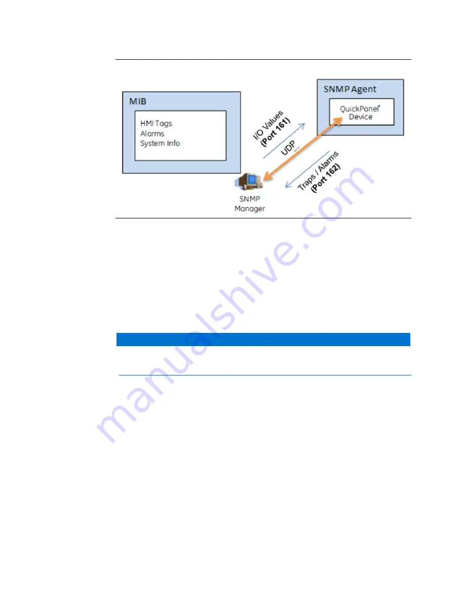
Figure 36: QuickPanel

+

 Operating as SNMP Agent 


QuickPanel

+

 Management Information Base (MIB) Overview 

The  QuickPanel

+

  SNMP  Agent  maintains  a  MIB  that  describes  the  managed  device 

parameters like HMI Tags, alarms, and such. The SNMP Manager uses the MIB to request 
specific information for the SNMP Agent and translates the information as needed for the 
SNMP Managers or Network Management System (NMS). 

The MIB is a collection of information for managing network elements. It is a plain text file, 
self-explanatory, and prepared based on the Structure of Management Information (SMI), 
an adapted subset of Abstract Syntax Notation One (ASN.1) standard and notation. 


The QuickPanel

+

 MIB follows the SNMP V2c and is also be compatible with SNMP V1 

based on the strictness of MIB compilers supported by SNMP Managers. 


The MIB is comprised of managed objects identified as Object Identifier (Object ID or OID). 
Each Identifier is unique and denotes specific characteristics of a managed device. When 
queried, the return value of each identifier may be different. Figure 37 displays the MIB tree 
structure and the private enterprise number allocated by the Internet Assigned Numbers 
Authority (IANA) for the EMERSON SNMP products and OID for the QuickPanel

+

 MIB:  


OID for GEIP node: .1.3.6.1.4.1.24893 


OID for qppMIB node: .1.3.6.1.4.1.24893.1.5.2.1.1 


NOTICE


Summary of Contents for QuickPanel+ IC755C S06RD Series

Page 1: ...USER MANUAL GFK 2847Y Aug 2020 QuickPanel TM OPERATOR INTERFACE USER MANUAL IC755CxS06RDx 6 Display IC755CxW07CDx 7 Display IC755CxS10CDx 10 Display IC755CxS12CDx 12 Display IC755CxS15CDx 15 Display ...

Page 2: ...3 2 Backup Utility 17 3 3 Storage Manager 17 3 4 Copy Project to SD Card 17 3 5 PAC Machine Edition Project Update 18 3 6 FTP Server 18 3 6 1 Remote User Authentication 19 3 6 2 FTP with Removable Flash Devices 19 3 7 HTTP Server 19 3 8 SNTP Server 20 3 9 QuickPanel OS Utilities Settings Tool 20 3 9 1 Firmware Upgrade 21 3 9 2 Bypass Startup Programs 23 3 9 3 Reset Enhanced Security 25 3 9 4 Enabl...

Page 3: ... Installation 49 5 1 Protective Sheet Installation 49 5 2 Mounting Location 49 5 3 Panel Mounting 50 5 4 Mounting and Installation Procedure 52 5 5 VESA Arm Mounting 55 5 6 Battery Installation and Replacement 56 5 6 1 IC755CxS06RDx 57 5 6 2 IC755CxW07CDx 59 5 6 3 IC755CxSxxCDx 60 5 7 Connectors 62 5 7 1 Power Connector Pin Out for IC755CxS06RDx IC755CxW07CDx and IC755CxSxxCDx 62 5 7 2 Ethernet fo...

Page 4: ...ional 77 7 1 Secomea Configuration Tool 77 7 2 Secomea Products 77 Chapter 8 Save and Restore Settings 80 8 1 Menu Item Location 80 8 2 Import Registry Data from XML File 82 8 3 Save the Settings to a File 83 8 4 Restore the Settings from a qps File 85 Appendix A Product Certifications and Installation Guidelines 87 A 1 Agency Approvals 87 A 2 Conditions of Safe Use for Installation in Hazardous L...

Page 5: ... maintenance The information is supplied for informational purposes only and Emerson makes no warranty as to the accuracy of the information included herein Changes modifications and or improvements to equipment and specifications are made periodically and these changes may or may not be reflected herein It is understood that Emerson may make changes modifications or improvements to the equipment ...

Page 6: ... can connect to most industrial equipment using the QuickPanel communications ports The QuickPanel is equipped with several memory types to satisfy the most demanding applications A section of Dynamic Random Access Memory DRAM is split between the operating system an object store and application memory Additionally a section of Non volatile Random Access Flash Memory NOVRAM functioning as a virtua...

Page 7: ...ch Panel Type Analog Resistive Multi touch Single touch Communications Ethernet Port 1x10Base T 100Base TX Serial Port 1x RS 232C COM1 5 pin connector USB Host 2x USB 2 0 Type A maximum power 5 V at 0 5 A USB Device 1x USB 2 0 mini Type B Storage 1x SD SDHC card slot Audio 1x Mic In Mono 3 5 mm jack 1x Line Out Stereo 3 5 mm jack Noise Immunity Noise Voltage 1500 V p p Pulse Duration 1µs Rise Time...

Page 8: ...Panel Type Projected capacitive Multi touch Two point Communications Ethernet Port 1x 10 100Base T RJ 45 Serial Port 1x RS 232 UART port 5 pin connector USB Host 2x USB 2 0 Type A maximum power 5 V at 0 5 A USB Device 1x USB 2 0 mini Type B Storage 1x SD SDHC card slot Audio 1x Mic In Mono 3 5 mm jack 1x Line Out Stereo 3 5 mm jack Noise Immunity Noise voltage 1500 V p p Pulse duration 1µs Rise ti...

Page 9: ...mmunications EthernetPort 2x 10 100Base T RJ 45 SerialPort 1x RS 232UARTport 1x RS 232 485port 2x 5 pin connector USB Host 2x USB2 0 Type A maximumpower 5 Vat 0 5 A USB Device 1x USB2 0 mini Type B Storage 1x SD SDHCcard slot Audio 1x Line Out Stereo 3 5 mm jack NoiseImmunity Noisevoltage 1500V p p Pulse duration 1µs Rise time 1ns Inputpower RatedVoltage 12 24 Vdc 20 3 pin connector PowerConsumpti...

Page 10: ...Base T RJ 45 1x 10 100Base T RJ 45 for IC755CxS12CDA SerialPort 1x RS 232UARTport 1x RS 232 485port 2x 5 pin connector 1x 10 pin connectorfor IC755CxS12CDA USB Host 2x USB2 0 Type A max power 5 Vat 0 5 A USB Device 1x USB2 0 mini Type B Storage 1x SD SDHCcard slot Audio 1x Line Out Stereo 3 5 mm jack NoiseImmunity Noisevoltage 1500V p p Pulse duration 1µs Rise time 1ns Inputpower RatedVoltage 12 2...

Page 11: ...unications EthernetPort 2x 10 100Base T RJ 45 SerialPort 1x RS 232UARTport 1x RS 232 485port 2x 5 pin connector USB Host 2x USB2 0 Type A maximumpower 5 Vat 0 5 A USB Device 1x USB2 0 mini Type B Storage 1x SD SDHCcard slot Audio 1x LineOut Stereo 3 5 mm jack NoiseImmunity Noisevoltage 1500 V p p Pulse duration 1µs Rise time 1ns Inputpower RatedVoltage 12 24 Vdc 20 3 pin connector PowerConsumption...

Page 12: ...ironment PollutionDegree2 Indooruseonly Vibration Resistance 5 to 9 Hz single amplitude3 5 mm 9 to 150 Hz constant accelerated velocity9 8m s2 X Y Z directions10 time 100 minutes Compliance3502 IEC61131 2JIS B Altitude 800 1114hPa altitudeup to 2000 m 6561 68ft RoHS Compliantwith EU RoHSDirective2011 65 EU Enclosure Rating ULType4X rating IP65 in panel mountonly Note For additional product standar...

Page 13: ...ace Installation and Maintenance Requirements IMR GFK 2981 Added the procedure for USB retaining clamps used in hazardous location installations for 7 Display units 1 4 PACSystems Documentation PACSystems Manuals PACSystems RX7i RX3i and RSTi EP CPU Reference Manual GFK 2222 PACSystems RX7i RX3i and RSTi EP CPU Programmer s Reference Manual GFK 2950 PACSystems RX7i RX3i and RSTi EP TCP IP Ethernet...

Page 14: ... Modules GFK 2235 Field Agent Manuals Field Agents User Guide GFK 2993 Field Agents Upgrade Guide GFK 3017 In addition to these manuals datasheets and product update documents describe individual modules and product revisions The most recent PACSystems documentation is available on the Emerson support website http www Emerson com Industrial Automation Controls ...

Page 15: ...LED indicators 2 1 Physical Characteristics In addition to the primary touchscreen interface the QuickPanel Operator Interface supports a variety of communication ports The following diagrams illustrate the physical layout of the QuickPanel Operator Interface including locations of status LEDs communications ports and connectors Figure 2 4 Sided View of IC755CxS06RDx ...

Page 16: ...User Manual Chapter 2 GFK 2847Y Aug 2020 Hardware 11 Figure 3 Rear View Dimensions IC755CxS06RDx Figure 4 4 Sided View IC755CxW07CDx ...

Page 17: ...User Manual Chapter 2 GFK 2847Y Aug 2020 Hardware 12 Figure 5 Rear View IC755CxW07CDx Note Refer to the section IC755CxW07CDx Specifications for drawing dimensions Figure 6 4 Sided View IC755CxS10CDx ...

Page 18: ...User Manual Chapter 2 GFK 2847Y Aug 2020 Hardware 13 Figure 7 Rear View IC755CxS10CDx Note Refer to the section IC755CxS10CDx Specifications for drawing dimensions Figure 8 4 Sided View IC755CxS12CDx ...

Page 19: ...User Manual Chapter 2 GFK 2847Y Aug 2020 Hardware 14 Figure 9 Rear View IC755CxS12CDx Note Refer to the section IC755CxS12CDx Specifications for drawing dimensions Figure 10 4 Sided View IC755CxS15CDx ...

Page 20: ...LED indication for the following Operation status Ethernet Port operation 2 2 1 Operation Status LEDs The QuickPanel has one tri color LED that provides visual operation status indication for IC755CxS06RDx IC755CxW07CDx the and IC755CxSxxCDx units LED State QuickPanel State Amber solid Operatingsystemstarting Green solid Normaloperatingstate Green blinking Backlightoff Red blinking Backlightfailur...

Page 21: ...r 2 GFK 2847Y Aug 2020 Hardware 16 2 2 2 Ethernet Port Operation LEDs The Ethernet port has two LED indicators Speed and Link Activity LED LED State OperatingState Speed Yellow on 10 100 Link Activity Green on Linkstatus ...

Page 22: ...Utility feature saves the changes made to the Windows Registry or Desktop to Flash Memory The Backup Utility achieves the following Stores the Windows Embedded Compact 7 registry including any control panel settings in Flash memory Stores changes or additions made to the Windows sub tree of the file system in the user block of flash memory 3 3 Storage Manager Note Storage Manager is accessed from ...

Page 23: ...n application that is currently stored on the QuickPanel unit with a revision stored on a flash device such as an SD card To update a Machine Edition project 1 Insert the flash device containing an upgraded version of the PAC Machine Edition project into the appropriate port 2 Restart the unit Note Depending on set options the update may or may not be enabled or may update automatically If there i...

Page 24: ...ces All removable flash devices remote FTP users as directories off the FTP root directory Computer Flash card partitions display as directories such as SD Memory and USB Flash Keys display as directories such as Hard Disk Full access privileges are granted for the client in these folders devices Removable flash device directories are captured when a session is opened and are not changed while the...

Page 25: ...d Note The DIP Switch feature is designed as a security measurement However security requirements can also be met using the gesture based feature Prior to the listed firmware builds these operations were only supported using the DIP Switch settings Some operators find it difficult to use the DIP Switch settings to perform these functions such as removing the back plate of the device and adjusting ...

Page 26: ... over Ethernet or Serial interfaces Insert the media SD Card containing the required files for firmware upgrade and perform the following procedure Note Make sure the copy of required binaries to the SD card is not within a folder The firmware package contains encrypted nbo files Use the PreUpdate exe tool to decrypt the nbo files before using them for upgrade After a firmware upgrade which refres...

Page 27: ...e project and install any site specific tools including third party tools on the device Firmware Upgrade for Specific Build Version The following procedure is applicable to the following QuickPanel display units QuickPanel IC755CxS06RDx 6 Display with Build14_14B QuickPanel IC755CxW07CDx 7 Display with Build37_37D QuickPanel IC755CxS10CDx 10 Display IC755CxS12CDx 12 Display and IC755CxS15CDx 15 Di...

Page 28: ...eboot and Run Program Message 3 9 2 Bypass Startup Programs Note This utility functions the same as disabling or enabling the Don t startup Program functionality using DIP Switch Position 2 The Bypass Startup Programs utility enables the operator to choose the gesture based feature or DIP Switch Use DIP Switch feature to perform the Force Startup operation To bypass startup programs and force star...

Page 29: ...User Manual Chapter 3 GFK 2847Y Aug 2020 Software 24 Figure 15 Activate Checkbox for Use DIP Switch Figure 16 Enable Bypass Sequence Figure 17 Start Up Window following Enable ...

Page 30: ...ad operation Every operation to connect to the device requires a password If you forget or do not know your password the Reset Enhanced Security feature enables a QuickPanel configuration download on the device by permitting the user to disable the Enhanced Security feature using the double tap feature Note Prior to support of the QuickPanel OS Utilities Settings Tool if the user forgot or did not...

Page 31: ...lic network SNMP communication is disabled by default on the QuickPanel device for security reasons As a security measure the SNMP feature requires a tactile input gesture to enable and disable SNMP communication Note Refer to the section Simple Network Management Protocol SNMP for further details Enabling or disabling SNMP communication is a one time user configuration To enable the SNMP Agent 1 ...

Page 32: ...alog box To disable the SNMP Agent 1 From the Start menu select Programs System and QuickPanel OS Utilities Settings Tool to display the QuickPanel OS Utilities Settings window 2 Disable SNMP communication Figure 22 Sequence to Disable SNMP 3 10 Display Screen Sensitivity Tool The QuickPanel 7 10 12 and 15 display units use capacitive screen technology that is far more responsive than the previous...

Page 33: ...press down more firmly to place the finger closer to the screen which causes the finger pad to spread out slightly to make a larger capacitive area Note Gloved operation works best when the operator is wearing gloves that fit If the fingers do not extend to the end of the glove the empty space at the fingertip may make it difficult to operate the display screen while wearing gloves Setting the scr...

Page 34: ...ator Interface from a laptop computer or a mobile device through the remote VNC Viewers User authentication of the VNC Server in the QuickPanel is determined by the configuration of the Enhanced Security feature on the device If the Enhanced Security feature is enabled for the device a VNC Viewer can connect to the QuickPanel on the VNC Server Connection is dependent upon user authentication with ...

Page 35: ...ction The QuickPanel Operator Interface provides an estimated lifespan of the battery in the device To display the battery life prediction the current time on the QuickPanel device must be set If a battery is not present the QuickPanel BatteryStatus tab cannot provide battery life prediction To display the battery life prediction from the Start menu select System open the QuickPanel Setup tool and...

Page 36: ...t Set Message 2 After setting the current time open the QuickPanel Setup Tool and select the BatteryStatus tab to display the correct battery life prediction information Figure 29 Example of Battery Life Prediction Displayed After Current Time Set 3 If the battery was replaced or removed on the QuickPanel QuickPanel Setup Tool BatteryStatus displays two possible scenarios related to the battery Th...

Page 37: ... the device Figure 31 Battery is Not Present Message 5 If the option the battery was replaced is selected enter the date of when the battery was first used in a QuickPanel device This date should reflect the date of first use in any QuickPanel device not just the current device Figure 32 Calendar Entry of Date for Battery was Replaced Option 6 Enter the current date Figure 33 Enter Current Date Op...

Page 38: ...ng management information between network devices It is a part of the Transmission Control Protocol Internet Protocol TCP IP suite The QuickPanel Operator Interface is enabled as an SNMP Agent with the capability to communicate with SNMP Managers software tools run independently and are not part of QuickPanel Operator Interface for the following purposes Send notification of HMI Alarms as Traps Pr...

Page 39: ...ucture of Management Information SMI an adapted subset of Abstract Syntax Notation One ASN 1 standard and notation The QuickPanel MIB follows the SNMP V2c and is also be compatible with SNMP V1 based on the strictness of MIB compilers supported by SNMP Managers The MIB is comprised of managed objects identified as Object Identifier Object ID or OID Each Identifier is unique and denotes specific ch...

Page 40: ...Download the MIBs GEIP SMI txt and GEIP PRODUCTS MIB txt from the Support Site QuickPanelMIB mib may be copied from the QuickPanel device by performing the procedure Export MIB to SD Card Figure 38 displays the HMI Alarms notification TRAP information with alarm objects as part of the Alarm Record The SNMP Manager is notified with the TRAP information when alarms are generated on the HMI running o...

Page 41: ...om the HMI running on a QuickPanel device Note The list of all HMI tags is populated within the hmiTags node of MIB tree and the HMI Tag access level is currently restricted to Read only for the SNMP Manager OID for starting HMI Tag element also called Index element 1 3 6 1 4 1 24893 1 5 2 1 1 50 1 1 If there were 40 HMI tags in total the last OID would be 1 3 6 1 4 1 24893 1 5 2 1 1 50 1 40 ...

Page 42: ...kPanel device to operate as an SNMP Agent and establish communication with an SNMP Manager Section 3 14 1 Configure Trap Destinations Section 3 14 2 Enable or Disable SNMP Agent Section 3 14 3 Export MIB to SD Card Section 3 14 4 Load MIB into SNMP Manager Section 3 14 5 Data Types Mapping between PAC Machine Edition Project and SNMP Section 3 14 6 Establish SNMP Communication ...

Page 43: ...re enable the SNMP Agent service on the device 1 From the Start menu select System open the QuickPanel Setup Tool and select the SNMP Agent tab 2 Configure the Trap destination s of the SNMP Manager Figure 40 Specify IP Address es as Trap Destination s 3 Click OK to save the changes Close the QuickPanel Setup Tool then re open the tool to view the configured Trap Destination details from the SNMP ...

Page 44: ...into SNMP Managers to avoid any MIB compiler errors Download the MIBs GEIP SMI txt and GEIP PRODUCTS MIB txt from the Support Site QuickPanelMIB mib may be copied from the QuickPanel device by performing the following procedure To export the MIB to an SD Card 1 Insert a working SD Card into the external card slot on the QuickPanel device 2 From the Start menu select System open the QuickPanel Setu...

Page 45: ... SNMP Manager tool File menu select Load the MIBs Figure 43 Loading MIBs in 3rd Party SNMP Manager Tool If there are no errors the MIB will be loaded successfully and the SNMP Manager will be ready for communication with QuickPanel device operating as an SNMP Agent 3 14 5 Data Types Mapping between PAC Machine Edition Project and SNMP When you configure HMI tags in a PAC Machine Edition project an...

Page 46: ...REAL variable LREALVar data type as R100 INT This maps LREALVar to DISPLAYSTRING in the MIB file 3 14 6 Establish SNMP Communication SNMP communication requires that both the QuickPanel device and the SNMP Manager running on a machine are connected on a valid Ethernet network To establish SNMP communication with the QuickPanel device 1 Download the Project to the network connected QuickPanel devic...

Page 47: ...uickPanel OS Utilities Setting tool 3 15 ScreenSaver QuickPanel has the ability to run a video as a screensaver The configuration for this can be done at the ScreenSaver Tab in the QuickPanel Setup Tool window Figure 44 Screen Saver Options The dialog box provides the following options 1 Enabling Disabling the ScreenSaver 2 Browsing the video file to be run as the ScreenSaver 3 The elapse idle tim...

Page 48: ...rrier It is the consignee s responsibility to register a claim with the carrier for damage incurred during shipment Note For phone numbers and email addresses refer to the section Contact Information at the start of this manual After unpacking the unit record all serial numbers These are needed to contact Customer Care during the warranty period Save all shipping containers and packing material fo...

Page 49: ...the supplied quick connect plug Depending on the application you may also want to connect and configure optional input devices communications ports and expansion adapters WARNING To avoid personal injury or damage to equipment ensure that the dc supply is disconnected from power and the leads are not energized before attaching them to the unit s power supply input If this equipment is used in a ma...

Page 50: ...for current carrying capacity and loss according to local regulations At a minimum the cable must be rated for 75 C 167 F or more USB compatible keyboard optional USB compatible mouse optional 4 3 1 Connecting Input Power To connect input power 1 Verify that the power cable is not energized 2 Loosen the screw clamps on the mating power connector 3 Strip the insulation from the power cables 4 Secur...

Page 51: ...ompact 7 operating system starts automatically 4 3 2 Initial Configuration Perform the following procedure during initial startup To configure the QuickPanel display 1 Tap Start point to Settings then tap Control Panel 2 Configure the system clock Figure 48 Set System Clock 3 From the Control Panel double tap System to configure a Network Device Name Many applications including Proficy Historian r...

Page 52: ...and issues addressed Firmware updates for the QuickPanel are available on the Support website Default DIP Switch Settings Note The firmware update will remove the application and change the IP Address of the QuickPanel Operator Interface The firmware package contains encrypted nbo files Use the PreUpdate exe tool to decrypt the nbo files before using them for upgrade 4 6 Shutdown There are no spec...

Page 53: ...gs for example brightness or touchscreen sensitivity or do not want to save the changes remove ac power from the dc supply 3 Run the Backup Utility to save changes to operating system settings When the Backup window displays Completed Successfully remove power from the dc power supply connected to the QuickPanel unit ...

Page 54: ...t or fingerprints 3 Peel back a corner of the clear side of the protective sheet 4 Begin applying the corner to the display screen 5 Slowly apply the rest of the protective sheet smoothing out as you go 6 Peel the green curing film from the protective sheet 5 2 Mounting Location Note Refer to Section 1 1 2 Environmental Specifications When mounting the QuickPanel Operator Interface make sure the m...

Page 55: ...el Mounting To mount the QuickPanel in an enclosure you will need the following equipment One 2 Phillips head screwdriver Mounting brackets supplied The mounting holes for IC755CxS06RDx IC755CxW07CDx and IC755CxS10CDx are located on the top and bottom edges of the unit Figure 50 Mounting Holes top bottom edges IC755CxS06RDx ...

Page 56: ...Mounting and Installation 51 Figure 51 Mounting Holes top bottom edges IC755CxW07CDx Figure 52 Mounting Holes top bottom edges IC755CxS10CDx The IC755CxS12CDx and IC755CxS15CDx mounting holes are located on the top bottom and sides of the unit ...

Page 57: ...part number listed in Appendix B The enclosure should be of metal material The metal enclosure panel should ensure proper thickness and rigidity suitable to minimize impact to the QuickPanel unit The recommended torque for the plastic back cover and interior metal cover for the 10 12 and 15 QuickPanel display units that is accessed for panel updates and serial port DIP Switches is 0 5 Nm 4 4 in lb...

Page 58: ...nto the panel pay careful attention while handling the unit so it does not drop and damage the unit To install the QuickPanel 1 Cut an opening in the panel according to the specifications in the following figures Note Panel cutout tolerances are 0 50 0 00 mm 0 02 0 00 in Figure 55 Panel Cutout Dimensions IC755CxS06RDx or IC755CxW07CDx Figure 56 Panel Cutout Dimensions IC755CxS10CDx Figure 57 Panel...

Page 59: ...he gasket is present and properly seated in the bezel channel located on the sides of the unit 3 Insert the QuickPanel into the mounting panel cutout Figure 59 Insert QuickPanel into Mounting Panel Cutout 4 Insert the hook of the mounting bracket into the mounting hole as displayed in the following figure Figure 60 Align and Set Hook ...

Page 60: ... Video Electronics Standards Association VESA MIS D arm stand or apparatus that complies with the UL1678 standard Note Refer to the mounting arm manual for instructions To VESA mount the QuickPanel unit use the mounting holes located on the back of the unit refer to Figure 62 and Figure 63 The mounting holes for IC755CxS06RDx and IC755CxW07CDx attach with M4 screws that are 6 mm 0 24 in or less in...

Page 61: ...ure 63 VESA Mounting Holes IC755CxSxxCDx 5 6 Battery Installation and Replacement WARNING Batteries may present a risk of fire explosion or chemical burn if mistreated Do not crush disassemble short circuit or dispose of in fire Use of batteries not specified for use with the QuickPanel product may present a risk of fire or explosion ...

Page 62: ...owered off 4 Care should be taken to protect and insert the battery with correct polarity 5 Do not use any metallic item to remove the battery such as screwdrivers knives pliers and so forth 6 Be careful to not drop the battery or any associated screws into the unit 7 Be careful of edges on internal sides of the enclosure and frame Attention The PC controller does not start automatically when the ...

Page 63: ...RDx 2 Connect the battery harness connector to the header noting keyed orientation Figure 65 Battery Harness Connection IC755CxS06RDx 3 Verify that the positive red is down and negative black is up 4 Wrap the harness connector around to match the following figure Do not let the harness connector go above the tab ...

Page 64: ...he harness connector 5 6 2 IC755CxW07CDx To install or replace the battery for the IC755CxW07CDx CAUTION Replace the battery for the IC755CxW07CDx only with Emerson battery part number IC755ACCBATT 1 Remove the battery cover by pressing down while sliding outward Figure 67 Battery Cover Removal IC755CxW07CDx 2 Connect the battery harness connector to the header noting keyed orientation ...

Page 65: ... harness connector around to match the following figure Do not let the harness connector go above the tab Figure 69 Harness Connector Orientation IC755CxW07CDx 5 Slide the battery cover into place taking care not to pinch the harness connector 5 6 3 IC755CxSxxCDx To install or replace the battery for the IC755CxSxxCDx CAUTION Replace the battery for the IC755CxSxxCDx only with Emerson battery part...

Page 66: ...r side tab to release the back cover Figure 71 Release Cover by Pressing Side Tabs IC755CxSxxCDx 3 Lift up and remove the back cover The battery will be exposed on the back of the unit Figure 72 Coin Battery Location IC755CxSxxCDx 4 Gently remove the coin battery and replace with a new one noting the polarity of the battery 5 Replace the battery cover and tighten all screws to 0 5 Nm 4 4 in lb ...

Page 67: ...play is equipped with 10Base T 100 Base TX Ethernet port s Connect an Ethernet network cable unshielded twisted pair CAT 5 to the unit through the RJ 45 connector s on the bottom of the enclosure LED indicators on the port indicate channel status The port can be accessed by Windows Embedded Compact 7 network communications or by your application Ethernet Port Details Interface Ethernet 10BASE T 10...

Page 68: ...ur network administrator for the QuickPanel IP Address Subnet Mask and Default Gateway if applicable Note Run the Backup Utility to save the settings 5 7 3 Serial Port Details IC755CxS06RDx Adhere to the following guidelines A terminal block is supplied with the unit The mating terminal block supports stranded 30 to 14 AWG 0 05 to 2 00 mm2 wires At a minimum the cable must be rated for 75 C 167 F ...

Page 69: ...th the unit The mating terminal block supports stranded 30 to 14 AWG 0 05 to 2 00 mm2 wires At a minimum the cable must be rated for 75 C 167 F or more Secure the serial cable to the mating connector while noting signal orientation and tighten the screw clamps The torque for the attaching screws is 0 3 Nm 2 66 in lb Serial Port COM1 Details Interface x1 RS 232 Connector Euro Terminal Tyco Electron...

Page 70: ...Dx Adhere to the following guidelines Terminal blocks are supplied The mating terminal blocks support stranded 30 to 14 AWG 0 05 to 2 00 mm2 wires At a minimum the cable must be rated for 75 C 167 F or more Secure the serial cable to the mating connector while noting signal orientation and tighten the screw clamps The torque for the attaching screws is 0 3 Nm 2 66 in lb Serial Port COM1 Details In...

Page 71: ...M2 Details Interface RS 232C 485 default is RS 485 Half duplex Pin Signal Name Pin Out RS 232C RS 485 Full duplex2 RS 485 Half duplex Figure 76 Serial Port COM2 Pin Out IC755CxSxxCDx 1 TXD TXD DATA 3 2 RXD TXD DATA 3 3 RTS RXD DATA 3 4 CTS RXD DATA 3 5 SGND SG SG 2 Full duplex RS 485 is backwards compatible with RS 422 mode 3 Pins 1 3 and 2 4 are connected internally in half duplex mode ...

Page 72: ... 4 OFF 4 OFF 5 ON 5 OFF 6 ON 6 OFF 7 OFF 7 OFF 8 ON 8 OFF SW3 1 ON SW5 1 ON 2 OFF 2 ON 3 OFF 3 ON 4 OFF 4 ON DIP Switch Settings COM2 for RS 422 DIPSW Bit ON OFF DIPSW Bit ON OFF SW2 1 OFF SW4 1 ON 2 OFF 2 ON 3 OFF 3 OFF 4 OFF 4 OFF 5 ON 5 ON 6 ON 6 ON 7 OFF 7 OFF 8 ON 8 OFF SW3 1 OFF SW5 1 OFF 2 ON 2 OFF 3 OFF 3 OFF 4 OFF 4 OFF Figure 77 Example of Full Duplex RS 422 Mode Connection ...

Page 73: ...ection 5 7 4 Universal Serial Bus USB Ports USB Host Port Details for IC755CxS06RDx IC755CxW07CDx and IC755CxSxxCDx The QuickPanel has two full speed USB 2 0 host ports A variety of third party USB peripheral devices are also available Each connected USB device requires a specific driver The driver supplied with the QuickPanel is for optional keyboard or mouse support other devices require install...

Page 74: ...B Adapters for All Models Using Adapters Recommended adapters are as follows Serial USB adapters based on FTDI chipset Ethernet USB adapters based on ASIX AX88179 or AX88772B Note For serial USB adapters USB to RS 485 and such configure the correct COM port depicted intheSystemInfotooland configurethe sameportintheDriver configuration IntheSystem Info tool the USB ports shown COM3 COM4 are based o...

Page 75: ...naural Number of Ports One Connectors Ø 3 5 mm jack Maximum output level 250 mVrms Pin Signal Name Pin Out 1 GND 2 Lineout R 3 Lineout L 5 7 7 SD Card Slot and Storage The QuickPanel is equipped with one standard SD Card port SD SDHC memory cards are supported The SD card slot is spring loaded for easy insertion and removal Note Micro SD slot is not supported on the 6 display unit IC755CxS06RDx Co...

Page 76: ...User Manual Chapter 5 GFK 2847Y Aug 2020 Mounting and Installation 71 Figure 79 SD Card Location IC755CxS06RDx Figure 80 SD Card Location IC755CxW07CDx Figure 81 SD Card Location IC755CxSxxCDx ...

Page 77: ...nu CAUTION Although Emerson recommends the use of the protective sheet do not operate the touchscreen with any hard materials such as a screwdriver This could damage the touchscreen display Note IC755CxS06RDx 6 display is an Analog Resistive touch display that does not support two point touch capability Single point gestures such as swipe pan and double tap are supported 6 1 1 Display Brightness A...

Page 78: ...ave the settings 6 1 3 Touchscreen Recalibration The QuickPanel touchscreen is shipped pre calibrated However if there are any issues with touchscreen responsiveness it may need to be recalibrated To recalibrate the touchscreen 1 Open the QuickPanel Setup tool 2 Select the TouchPanel tab 3 Select Recalibrate Touch Screen 4 Select Recalibrate Touch Sensor Note During IC755CxS06RDx or IC755CxW07CDx ...

Page 79: ... the operating system and no configuration is required To use an external keyboard connect the keyboard to the unit using the USB cable 6 2 2 Soft Input Panel The Soft Input Panel SIP is a touchscreen keyboard that may be used in place of a standard hardware keyboard An icon in the system tray enables the user to view or hide the SIP To show or hide the SIP from the system tray located on the task...

Page 80: ...multiple documents in its queue Windows Embedded Compact 7 does not support the ability to observe which documents are queued up at the printer For a list of printers that are compatible with that QuickPanel Operator Interface refer to the document Third Party Device Compatibility KB8259 6 5 Memory 6 5 1 DRAM Memory The QuickPanel Operator Interface is equipped with Dynamic RAM DRAM Part of the DR...

Page 81: ...r cycle It is recommended that the Storage Memory be set to a valid limit 6 5 2 Memory Allocation Modification To change the memory allocation 1 From the Control Panel double tap System to display the System Properties window 2 From the Memory tab drag the slider bar to divide into Storage and Program memory The amount of memory allocated to and used by each area is displayed in the window The blu...

Page 82: ...uickPanel on the Secomea network 1 From the QuickPanel Start menu select Programs to display the Secomea Configuration tool window 2 Enable the QuickPanel device on the Secomea network Figure 86 System Memory Slide Bar Display Note The Appliance Name can be any name but should be unique so that Secomea network can identify the device Proxy Address allows the user to connect from their local networ...

Page 83: ...d the encrypted traffic between LinkManagers and devices controlled by SiteManagers are handled by the GateManager where all events are also logged Note The GateManager is typically offered as a service hosted by Secomea Users will receive an isolated domain on the GateManager and benefit from central hosting and back up by Secomea Or the user can host their own GateManager Additionally other devi...

Page 84: ...User Manual Chapter 7 GFK 2847Y Aug 2020 Secomea Security Optional 79 Figure 87 Secomea Products used with QuickPanel in Application ...

Page 85: ...s feature box has two associated tabs 1 Settings and 2 Registry Settings Tab This tab has the different names of different settings that the user can select to save the settings value to the file Note 1 The settings tab of Save and Restore Settings dialog is not used for setting the values for any device parameters It is only used to make selection of the parameter settings that the user wants wis...

Page 86: ...QP Save Settings Registry Tab To update the value to a registry key the click on the Add button Figure 90 This displays dialog Figure 91 to enter the values for Key Path Name Type and value After entering the values click the OK button to close the dialog and the entered data may be viewed as a record in the Registry tab ...

Page 87: ...t button This opens the dialog box that allows the user to edit the data Figure 92 Registry List Display 8 2 Import Registry Data from XML File An alternate method to input the data to the registry is by using the Import option where the registry value data is available in an XML file and then imported using the Import option in the dialog The schema of the XML data can be seen in the screenshot b...

Page 88: ... Import XML Feature Note The feature does not support editing any registry keys inside HKEY_CLASSES_ROOT 8 3 Save the Settings to a File To save the settings and registry values to a file click on the Save button This displays the file save dialog allowing the user to select the folder location and provide the file name Click the OK button to complete the creation and saving of data to the file ...

Page 89: ...User Manual Chapter 8 GFK 2847Y Aug 2020 Save and Restore Settings 84 Figure 95 Saving the Settings and Registry Values to a File Figure 96 Save Function Successful Notification ...

Page 90: ...lowing steps need to be executed 1 Make sure that the file is browsable from the target QuickPanel 2 Click on the Restore button select Yes when prompted for confirmation 3 In the Open File dialog browse and select the qps file from which you would like to restore the data then click on the OK button Figure 97 Restore Function Figure 98 Browse to and Select qps File ...

Page 91: ...otification On clicking the Save or Restore button an Enhanced Security enabled QuickPanel device will prompt the user for the Enhanced Security password The corresponding operation will be executed only on successful authentication Figure 100 Password Entry Required for Enhanced Security Enabled QP ...

Page 92: ...sion 2 applicable to 6 Display unit only Certification by Underwriter s Laboratories to UL 61010 1 UL61010 2 201 CSA C22 2 No 142 M1987 CSA 61010 1 CSA 61010 2 201 ISA 12 12 01 standard and CSA C22 2 No 213 M1987 Explosive Atmospheres Directive European Safety for Hazardous Areas Equipment Group II Category 3 Gas Groups IIC Dust Group IIIC Certification in accordance with the ATEX Directive 14 34 ...

Page 93: ...all only be used in an area of at least pollution degree 2 as defined in IEC 60664 1 Note Pollution degree 2 can be achieved when the installation is in a controlled environment with suitably controlled condensation or airborne pollution 2 The equipment shall be installed in an enclosure that provides a minimum ingress protection of IP 54 in accordance with IEC 60079 0 3 Transient protection shall...

Page 94: ...retaining clamp to fit the cable size Figure 103 Adjust Retaining Clamp USB retaining clamp for IC755CSW07CDACA must be used in hazardous location installations as follows 1 Connect the USB retaining clamp plate Figure 104 Attach USB Retaining Clamp Plate 2 Connect the USB cable and insert the retaining clamp into the retaining clamp plate Figure 105 Insert Retaining Clamp into Retaining Clamp Pla...

Page 95: ... TO THE MINI USB MIC TERMINAL AS IT WILL INVALIDATE THE ATEX APPROVAL If this equipment is used in a manner not specified by the manufacturer equipment protection may be impaired A 3 EMC Installation and Operation Considerations This equipment is intended for industrial use only and complies with a minimum level of EMC performance as defined by EN 61000 6 2 and EN 61000 6 4 standards To meet these...

Page 96: ...mercial environment This equipment generates uses and can radiate radio frequency energy and if not installed and used in accordance with the instruction manual may cause harmful interference to radio communications Operation of this equipment in a residential area is likely to cause harmful interference in which case the user will be required to correct the interference at his own expense Changes...

Page 97: ...ack IC755CSS10CDx QuickPanel 10 Color TFT with Multi Touch Projected Capacitive Screen 12 24 Vdc Powered IC755ACC10GAS QuickPanel 10 Replacement Gasket IC755ACC10MNT QuickPanel 10 Accessory Kit Replacement Mounting Clips Power and Serial Port Connectors IC755ACC10PRO QuickPanel 10 Replacement Screen Protectors Qty 3 IC755CSS10CDACA QuickPanel 10 with Conformal Coating IC755CSS12CDx QuickPanel 12 C...

Page 98: ...l cable to the mating connector while noting signal orientation and tighten the screw clamps The torque for the attaching screws is 0 3 Nm 2 66 in lb Interface x1 RS 232 x1 RS 232 485 default is RS 485 Connectors Euro Terminal Tyco Electronics 1 284539 0 Mating Connector Tyco Electronics 1 284510 0 Pin Signal Name Pin Out COM1 RS 232 Figure 107 Serial Port Pin Outs IC755CxS10CDx IC755CxS12CDA and ...

Page 99: ...rightto modifyorimprove the designs orspecifications ofthe products mentioned inthis manual at any time without notice Emerson does not assume responsibility for the selection use or maintenance of any product Responsibility for proper selection use and maintenance of any Emerson product remains solely with the purchaser 2019 Emerson All rights reserved Emerson Terms and Conditions of Sale are ava...

Reviews: