Chapter 4 Use Of Monitoring Module M500D 31
4.7.8 DC Settings
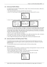
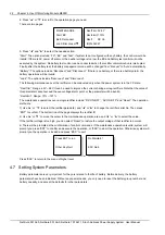
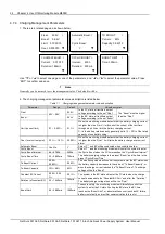
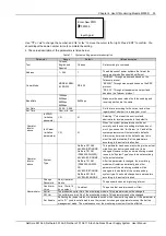
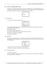
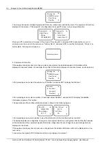
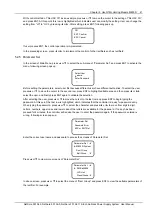
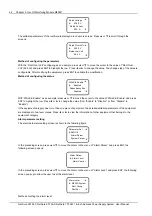
1. There are three related pages, as shown below:
DC VOLT ALARM
Over: 58.5V
Low: 45.0V
Under: 45.0V
AMB.TEMP ALARM
High: 50
℃
Low: 0
℃
Load Shunt:
None
Shunt Coeff:
500A/ 75mV
Use “▼” or “▲” to select one page or one of the parameters, and “◄” or “►” to select the parameter value. Press
“ENT” to confirm and save.
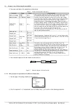
2. The value description of the parameters is listed below:
Table 1.1 DC setting parameter description
Parameter
Range
Default
Value description
Over (over-
voltage)
40V ~ 60V
58.5V
The “DC Over Voltage” alarm will be raised when the
system DC output voltage is higher than the value of
“Over”
The values of
these three
parameters should
be: Over > Low >
Under
Low (low-
voltage)
45.0V
The DC low voltage alarm will be raised when the system
DC output voltage is lower than the value of “Low”
Under (under-
voltage)
45.0V
The DC under voltage alarm will be raised when the
system DC output voltage is lower than the value of
“Under”
High (high
temperature)
10°C ~
100°C
40°C
The high temperature alarm will be raised when the
detected ambient temperature is higher than the value of
“High”
The value of
parameter “High”
must be higher
than that of
parameter “Low”
Low (low
temperature)
-40°C ~
10°C
-5°C
The low temperature alarm will be raised when the
detected ambient temperature is lower than the value of
“Low”
Load shunt
Y, None
None
Set according to the system actual situation
Shunt Coeff
Dependent on system
type
In the system with a load shunt, this parameter can be set only when the
parameter “Shunt” (as a system type) is set to “Set”
4.7.9 Rectifier Settings
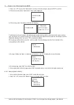
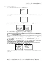
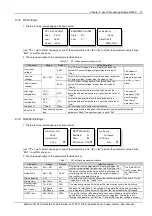
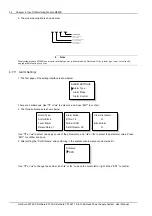
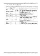
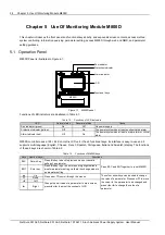
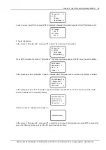
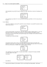
1. There are three related pages, as shown below:
Rect Over Volt:
59.0V
Default Volt:
42.0V
▼
RECT WALK-IN
Enabled: N
Time: 8s
CurrInLim: 30A
▼
Fan Speed:
Full Speed
HVSD Time:
300s
▼
Use “▼” or “▲” to select one page or one of the parameters, and “◄” or “►” to select the parameter value. Press
“ENT” to confirm and save.
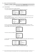
2. The value description of the parameters is listed below:
Table 1.1 DC rectifier parameter description
Parameter
Range
Default
Value description
Rect Over Volt
56V ~ 59V
59V
The rectifier over voltage alarm will be raised when the
rectifier output voltage is higher than the “Rect Over Volt”
The “Default Volt”
must be lower than
the “Rect Over
Volt”
Default Volt
48V ~ 58V
53.5V
When the communication between the rectifier and the
monitoring module is interrupted, the output voltage of
the rectifier is the default voltage
Walkin Enabled
Y, N
N
The output soft start function means the rectifier voltage will rise from 0V to the
“Default Volt” after the “Walkin Time”
Walkin Time
8s ~ 128s
8s
Rectifier input
current limit
1A ~ 50A
30A
The monitoring module limits the rectifier input current within the limit value
Fan Speed
Full Speed,
Half Speed
Half
speed
When set to “Half Speed”, the rectifier will regulate the fan speed according to
the temperature. When set to “Full Speed”, the fan will operate at full speed
HVSD Time
50s ~ 300s
300s
The rectifier will shut off automatically upon over-voltage, and restart after a
certain delay to see whether it is still over-voltage then. That delay is set
through the parameter “HVSD Time”. If the rectifier’s output voltage is normal
NetSure 501 A50, NetSure 501 AA0, NetSure 701 A51 19-Inch Subrack Power Supply System User Manual

