


6
Micro Motion
®
Model 2400S Transmitters with Analog Outputs
Using the Transmitter User Interface
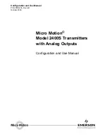
Figure 2-1
User interface – Transmitters without display
Figure 2-2
User interface – Transmitters with display
For information on the status LED, see Chapter 7.
For information on making a HART connection, see Chapter 4.
For information on making a service port connection, either through the service port clips or through
the infrared port, see Chapter 3.
For information on using the zero button, see Chapter 5.
Status LED
HART security switch
HART clips
Service port clips
Zero button
Current value
Unit of measure
Process variable
Scroll
optical switch
Select
optical switch
Optical switch indicator
Status LED
HART security switch
Infrared port
HART clips
Service port clips
LCD panel
Optical switch indicator
Summary of Contents for Micro-Motion 2400S
Page 8: ...vi Micro Motion Model 2400S Transmitters with Analog Outputs ...
Page 20: ...12 Micro Motion Model 2400S Transmitters with Analog Outputs ...
Page 30: ...22 Micro Motion Model 2400S Transmitters with Analog Outputs ...
Page 42: ...34 Micro Motion Model 2400S Transmitters with Analog Outputs ...
Page 66: ...58 Micro Motion Model 2400S Transmitters with Analog Outputs ...
Page 76: ...68 Micro Motion Model 2400S Transmitters with Analog Outputs ...
Page 138: ...130 Micro Motion Model 2400S Transmitters with Analog Outputs ...
Page 190: ...182 Micro Motion Model 2400S Transmitters with Analog Outputs ...
Page 197: ......