background image

Chapter 1    Product Description            1 

RDU-SIC G2 Card    User Manual 

Chapter 1   Product Description 

The RDU-SIC G2 card is a network management card. It can make the intelligent equipment (such as UPS, PDU, air 

conditioner and so on) developed by Vertiv have the capacity of network communication. The RDU-SIC G2 card can 

also connect to the environment monitoring equipment, including IRM series temperature & humidity sensor or dry 

contact signal input & detecting sensors. In case of an equipment alarm, it notifies the user by multiple ways: recording, 

sending a Trap message, sending an E-Mail or sending an SMS. 

The RDU-SIC G2 card can meet the requirements of TCP/IP, RS232/485 networking modes and can be flexibly 

configured according to various application conditions. 

This chapter expounds the components description, main functions and technical specification. 

1.1   Components Description 

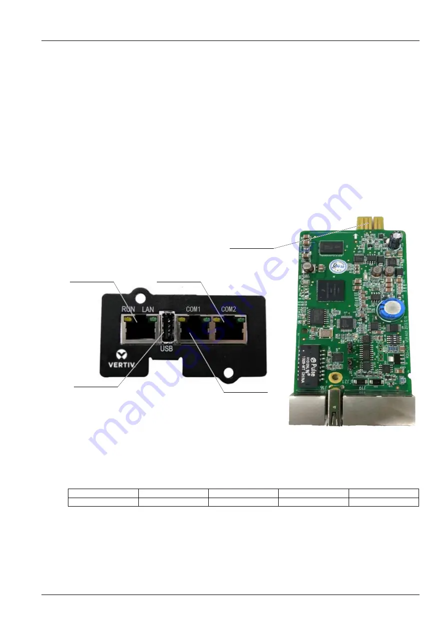
The appearance and ports of the RDU-SIC G2 card are shown in Figure 1-1. 


Figure 1-1    Appearance and ports of RDU-SIC G2 card 

Console port 

The RDU-SIC G2 card supplies a console port (USB port, see Figure 1-1 for its position), which adopts USB 

communication mode. Short pin 2 and pin 3 of jumper J20. The communication parameters are given in Table 1-1. 

Table 1-1    Communication parameters of console port 

Parameter 

Baud rate 

Bit 

Parity 

Stop bit 

Value 

115200bps 

8 bits 

None 

1 bit 


USB port 

The RDU-SIC G2 card supplies one USB-A type socket port for connecting USB Modem of designated model. Short 

pin 1 and pin 2 of jumper J20. Its position is shown in Figure 1-1. 


Ethernet port


1) 


RDU-M


2) 


SMTP


3) 


NSM management system


4) 


Web browser


RS485 port


1) 


PDU


2) Air conditioner


3) 


UPS


4) 


IRM sensor


USB port


1) 


Connecting USB Modem


2) Equipment console port


RS485 port


1) 


PDU


2) Air conditioner


3) 


UPS


RS485/RS232 port


1) 


PDU


2) Air conditioner


3) 


UPS


Summary of Contents for Liebert Vertiv RDU-SIC G2

Page 1: ...ess Connectivity 6 3 1 2 Checking Browser Version 6 3 1 3 Checking Browser Setting 6 3 2 Log In RDU SIC G2 10 3 2 1 Login Page 10 3 2 2 Forgetting Password 10 3 3 Homepage Of RDU SIC G2 11 3 3 1 Time Calibrating Link 12 3 3 2 Clearing Time Out 12 3 3 3 Logout 12 3 3 4 Real Time Alarm Pop Up Setting 12 3 4 Menu Items 12 3 4 1 Device Information 13 3 4 2 Safe Shutdown 14 3 4 3 Alarm Management 16 3 ...

Page 2: ......

Page 3: ...ption main functions and technical specification 1 1 Components Description The appearance and ports of the RDU SIC G2 card are shown in Figure 1 1 Figure 1 1 Appearance and ports of RDU SIC G2 card Console port The RDU SIC G2 card supplies a console port USB port see Figure 1 1 for its position which adopts USB communication mode Short pin 2 and pin 3 of jumper J20 The communication parameters ar...

Page 4: ...tenance policy of the UPS and can periodically reboot or close the supervised UPS Sever shutdown Used together with the NetworkShutdown software When the UPS has certain critical alarm the system will notify the server shutdown to avoid the sever going down Alarm Management Current alarm Displaying alarm in real time and confirming the current alarm History alarm Querying the history alarm Alarm n...

Page 5: ...3 Technical Specifications 1 3 1 Environment Specifications See Table 1 5 for the environment specifications of RDU SIC G2 Table 1 5 Environment conditions Item Requirement Application location Usually in data center or computer room with air conditioner Working temperature 10º C 60º C Relative humidity 5 RH 95 RH no condensing Working environment Dust compliant with the indoor requirements of GR ...

Page 6: ...2 1 Jumper J18 Jumper J20 Figure 2 1 Jumper locations of the RDU SIC G2 card Make sure that the jumpers of RDU SIC G2 card are set to correct position See Table 2 1 for the jumper setting of the RDU SIC G2 card Table 2 1 Jumper setting of the RDU SIC G2 card Working mode Jumper setting Description Maintenance mode J20 J18 The USB port is used to login the RDU SIC G2 card through Hyper Terminal TTY...

Page 7: ...othes wash hands with water and dry them Immunity Take the following measures for immunity Keep the working ground of RDU SIC G2 away from earthing device of electricity device or SPD earthing device Keep away from the radio transmitting station radar transmitter and high frequency large current device Use the electromagnetic shielding method if necessary 2 2 Installing RDU SIC G2 Card 1 Set the j...

Page 8: ...e test method 3 1 2 Checking Browser Version For the best user experience the recommended browser is Internet Explorer its version includes IE8 IE9 IE10 or IE11 you can also use other pop web browsers such as Chrome Firefox 3 1 3 Checking Browser Setting Checking IE General setting Double click the icon of IE to run the software click the menus of Tools Internet Options then click the Settings but...

Page 9: ...ure 3 3 Figure 3 3 LAN setting 3 Consult the network manager of your area ask if you need to set a proxy server and get the configuration method If there is no need to set a proxy server do not tick any option Checking IE security setting 1 Double click the icon of IE to run the software click the menus of Tools Internet Options and then choose the Security tab to pop up the window shown in Figure...

Page 10: ...ose Local intranet and click the Custom level button to pop up the window shown in Figure 3 5 Figure 3 5 Security setting 2 3 In the window shown in Figure 3 5 set Medium low for the security level Click the Reset button to finish Reset custom settings at last click OK 4 In the window shown in Figure 3 6 set Enable for File download ...

Page 11: ...bling file download 5 In the window shown in Figure 3 7 set Enable for Initialize and script ActiveX controls not marked as safe for scripting Figure 3 7 Enabling ActiveX controls 6 In the window shown in Figure 3 8 add the IP address of the RDU SIC G2 into the trusted site list ...

Page 12: ...FAQ Crystal blue Ocean blue Figure 3 9 Login page of RDU SIC G2 2 On the login page select a preferable theme by clicking or means crystal blue means ocean blue as shown in Figure 3 9 3 Type the username and password default username admin default password Vertiv and click the Login button the homepage will appear as shown in Figure 3 11 3 2 2 Forgetting Password If you forget the password click t...

Page 13: ... sent by the system Refer to Alarm Notification in 3 4 3 Alarm Management for detailed setting method 2 The gotten password is a random new password generated by the system please modify the password after logging in the system successfully 3 3 Homepage Of RDU SIC G2 After successful login the homepage of RDU SIC G2 is displayed by default as shown in Figure 3 11 1 2 3 4 5 6 8 10 9 7 1 Menu item 2...

Page 14: ... verification 3 3 3 Logout Click the Logout at the upper right corner of the homepage the prompt box shown in Figure 3 14 will appear clicking OK will log out safely Figure 3 14 Logout 3 3 4 Real Time Alarm Pop Up Setting The real time alarm displaying list is contracted on the bottom of the page by default You can perform the following operation by referring to Figure 3 11 1 Click Display Current...

Page 15: ...onnected to RDU SIC G2 Sampling Clicking the Sampling tab can enter the sampling page which displays sampling signals of selected device as shown in Figure 3 15 Figure 3 15 Sampling signals If some signal is in alarm status it will be displayed in red Control Clicking the Control tab can enter the control page which displays control signals of selected device as shown in Figure 3 16 Figure 3 16 Co...

Page 16: ...homepage click the Safe Shutdown menu on the left two submenus appear including Shutdown Schedule and Server Shutdown Shutdown Schedule Click Shutdown Schedule under the Safe Shutdown menu the page shown in Figure 3 19 pops up Figure 3 19 Shutdown Schedule page The Shutdown Schedule page is used to add delete and modify schedule shutdown task of UPS devices As shown in Figure 3 19 type a task name...

Page 17: ...en the Open Mode is set to Do Not Open Device or Open Device At Once the Open Time cannot be set and it is displayed as 2 The format of ShutDown Time changes with different options of ShutDown Mode automatically as shown in Figure 3 22 Figure 3 22 Format of shutdown time Note 1 The RDU SIC G2 can support up to ten shutdown tasks 2 Only when Enable Device is set for Status can the schedule shutdown...

Page 18: ...ck the Alarm Management menu on the left three submenus appear including Current Alarm History Alarm and Alarm Notification Current Alarms Click Current Alarms under the Alarm Management menu or refer to 3 3 5 Real Time Alarm Pop Up Setting the current alarm list will pop up as shown in Figure 3 24 Figure 3 24 Current alarms 1 You can click the tabs above the alarm list to view current alarms acco...

Page 19: ...rm content including Equip name Alarm description Alarm TIME and Alarm state by default Click the Save button to finish the alarm configuration When an alarm is generated the system will notify users through the chosen notification method Note 1 Users must tick the notification method first in the Notification by check boxes and then the alarm table below can be edited 2 When all devices are chose...

Page 20: ... to save the configuration of current user s SMS Modem Note If the SMS Modem is connected through USB port you need to set the jumper by referring to Table 2 1 Email Server Configuration 1 Type the server IP address or domain name in the Email Server field 2 Type the Server Port Email User Email Password and Sender Email Address in the corresponding fields 3 Click the Save button to save the confi...

Page 21: ... Notification Enabled Period setting range 8 00 20 00 Notification Scheduled Cycle default Hour Interval of Notification default 1 and Send Time Setting default start time 3 Click the Save button to save the system notification configuration 3 4 4 Data History The Data History menu supplies query service of all types of historical data and logs for the user On the RDU SIC G2 homepage click Data Hi...

Page 22: ...hown in Figure 3 32 choose a device for instance All Devices and the log type for instance History Data and set the start time and the end time for instance from 2014 07 30 00 00 00 to 2014 07 30 23 59 59 Then click the Query button all the history data during the time will be listed click the Download button to download the query result 2 Historical Curve As shown in Figure 3 33 choose a device f...

Page 23: ...n all control logs during the time will be listed click the Download button to download the query result Note When the log type is selected as System Log or Driver Log after clicking the Query button the query result will not be displayed on the page instead it will be directly downloaded as a zip file 3 4 5 Device Options On the RDU SIC G2 homepage click Device Options in the left part three subm...

Page 24: ...ce has many models you need to type the model ID which must be numbers from 1 to xx The model IDs under one kind of device must be different 5 Choose or type the device location 6 Type the communication parameter in the Parameter textbox In the event that the device type is certain the communication parameter prompt information will appear in the Parameter textbox including the communication param...

Page 25: ...fied it cannot be deleted Modifying a device 1 Choose the device which needs to be modified in the device list 2 Modify the device information 3 Click the Modify button to make the setting effective 4 Click the Save Configuration button to make the settings become effective and the detailed procedures are the same as those of adding a new device After adding modifying or deleting procedures if you...

Page 26: ...igure 3 40 Figure 3 40 Confirming dialog box Click OK the dialog box of Security authentication pops up as shown in Figure 3 13 type the login password of current user and click OK to uninstall the corresponding equipment type Note 1 While installing device type if the device type exists and the device driver has a higher version than the driver to be added it cannot be installed repeatedly 2 If t...

Page 27: ...typed the prompt box shown in Figure 3 42 will pop up Figure 3 42 Prompt box of invalid characters Batch Configuration Click the Batch Configuration under the Device Options menu the page shown in Figure 3 43 pops up Figure 3 43 Batch configuration On the page you can perform Upload and Download operations to complete batch configuration Note 1 Only admin has the authority of batch configuration I...

Page 28: ... Outgoing Alarm Blocked when an alarm occurs it will be blocked in this case 1 For current alarms the page only displays the alarm signals but not send alarm notifications after the alarm disappears it will not be saved in history alarm 2 The Blocked setting for Outgoing Alarm Blocked will be automatically cleared in 24h Network Setting 1 IP Setting Click the Network Setting under the System Optio...

Page 29: ... if you select to use an agent you also need to configure the agent server 3 SNMP Configuration Click the Network Setting under the System Options menu and then click the SNMP Configuration tab you can configure SNMP agent The RDU SIC G2 system supports V2 and V3 versions of SNMP agent As shown in Figure 3 47 the specific setting method of SNMP V2 is as follows 1 Set NMS IP host IP address of SNMP...

Page 30: ...only DES is supported for Privacy Protocol 4 You need to self define Authentication Password and Privacy Password which contain at least 8 characters and be the same as the password set by the host of SNMP agent data receiving end or it cannot be decrypted and received After parameter setting click the Add button to add NMS If you need to modify NMS setting select the NMS which needs to be modifie...

Page 31: ...section for detailed setting method 3 Choose Frequency of Reporting Monthly Seasonal 4 Click OK to send the remote service request Cancel RDU remote used to cancel the established remote service Choose Cancel RDU remote and click OK to send a command to cancel the current remote service Note Canceling the remote service is effective only under the precondition that the remote service has been esta...

Page 32: ... letters digits and _ In addition the initial characters must be letters or digits Delete user 1 Choose the user which needs to be deleted in the username list 2 Click the Delete button to pop up the confirming dialog box as shown in Figure 3 51 Figure 3 51 Confirming dialog box 3 Click OK the dialog box of Security authentication pops up as shown in Figure 3 13 Type the login password of current ...

Page 33: ...ephone the test is successful if not the test fails please check that the telephone number is correct and the SMS Modem is properly connected Email Alarm Notify Test Type the email address in the Email field and click the Email Test button to test that the email address of current user is correct If users receive the test email the test is successful if not the test fails please check that the inf...

Page 34: ...estore operation make sure to wait two minute for the RDU SIC G2 conducting complete initializing work before re accessing it through Web Site Setting Click the Site Setting under the System Options menu the page shown in Figure 3 54 pops up Figure 3 54 Site information setting On the page shown in Figure 3 54 you can modify the site information of RDU SIC G2 including Site Name Site Location and ...

Page 35: ... As shown in Figure 3 56 you can replace the Logo picture in the upper right part by uploading system Logo picture Click the Browse button choose the needed Logo picture and click the Upload button to upload the file to RDU SIC G2 Only gif bmp jpg and png format pictures are allowed and the picture size should be less than 500K Clicking the Default button can restore the default Logo picture You c...

Page 36: ...pter 3 Web Page Of RDU SIC G2 RDU SIC G2 Card User Manual The About RDU SIC G2 page displays Software Version Serial Number and Identify Code of RDU SIC G2 as shown in Figure3 57 Figure 3 57 About RDU SIC G2 ...

Page 37: ...SIC G2 is powered on why the power indicator is not on A Please check that the power cable is connected correctly Q2 How to deal with that the communication of COM port is abnormal A Check that the COM ports on the RDU SIC G2 and the expansion card are RS 232 RS 485 adaptive ports please ensure that the communication parameters are correctly configured Q3 How to deal with that there is no access t...

Page 38: ...ick the User Logout button to return the login page click the icon to choose the ocean blue theme and log in the system again Q5 After an alarm is generated you do not receive any email or SMS notification or when the alarm does not finish the email or SMS notification is less than three times how to deal with it A Please perform troubleshooting according to the following procedures 1 Please check...

Page 39: ...uently Asked Questions FTP File Transfer Protocol used to transfer large chunks of data HTML Hypertext Mark Up Language used to create Web pages HTTP Hypertext Transfer Protocol used to convey HTML LED Light Emitting Diode Linux A UNIX like operating system with open source developed under Free Software Foundation FSF LLP Local Language Package LUI Local User Interface MA Moderate Alarm NA No Alar...

Page 40: ...uration List No Description Number Unit 1 RDU SIC G2 intelligent port monitoring card 1 EA 2 User manual RDU SIC G2 Card User Manual V1 1 Chinese English Version 16mo Glue Binding 1 EA 3 Whole set cable UH52SA1SL2 UH52SA1Z UPS USB cable ROHS 1 EA 4 Whole set or other labels certificate label 1 EA ...

Page 41: ... is outside the limits specified in SJ T11363 2006 Vertiv Tech Co Ltd has been committed to the design and manufacturing of environment friendly products It will reduce and eventually eliminate the harzardous substances in the products through unremitting efforts in research About Environment Protection Period The Environment Protection Period of the product is marked on the product Under normal w...

Reviews: