Installation, Operation and Maintenance Manual
MAC050515 EN Rev. 0
November 2022
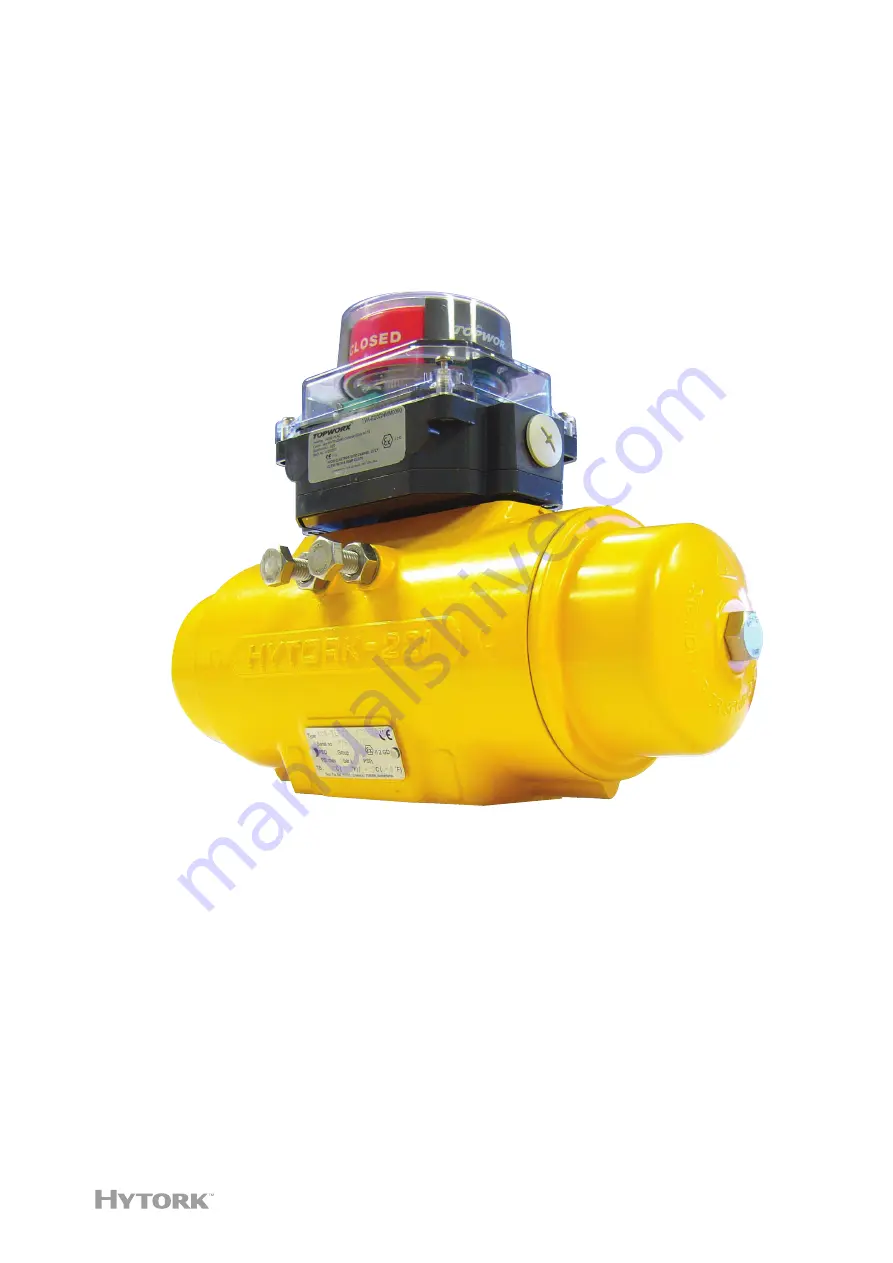
Hytork XL Pneumatic Actuator
Page 1: ...Installation Operation and Maintenance Manual MAC050515 EN Rev 0 November 2022 Hytork XL Pneumatic Actuator ...
Page 2: ...This page is intentionally left blank Notes November 2022 Installation Operation and Maintenance Manual MAC050515 EN Rev 0 ...
Page 3: ...Temperature Range 5 Section 4 Actuator to Valve Installation 4 1 Bi directional Travel Stops 6 4 2 Travel Stop Adjustment Procedure 7 Section 5 Piping Instructions Piping Instructions 8 Section 6 Solenoid Valves on Spring Return Actuators Solenoid Valves on Spring Return Actuators 9 Section 7 Position Feedback Position Feedback 10 Section 8 Spares Recommendations Spares Recommendations 11 Section ...
Page 4: ...Block Assembly 20 11 3 General Notes when Fitting to Valves 21 11 3 1 Double Acting 21 11 3 2 Standard Configuration Fail Safe Clockwise 21 11 3 3 Reverse Action Fail Safe Counterclockwise 22 11 4 Actuator Conventions for the Normal Position 22 11 4 1 Double Acting 22 11 4 2 Spring Return 22 11 5 Assembly to Valves for Standard Rotation Configuration 22 11 5 1 Double Acting and Fail Safe Clockwise...
Page 5: ... disconnect the air and electrical supplies before carrying out any form of maintenance on an actuator When removing any ball valve or plug valve assemblies from a pipe system isolate the piping system on which the actuator is installed and relieve any media pressure that may be trapped in the valve cavities before removing the actuator for maintenance Always contain the spring tension with Hytork...
Page 6: ...rapid temperature changes Actuators should not be stored on any floor surface On site storage Hytork actuators should be stored in a clean dry warehouse free from excessive vibration and rapid temperature changes Prevent moisture or dirt entering the actuator Plug or seal both air connection ports WARNING Use lifting equipment as required by national or local legislation Use lifting straps to lift...
Page 7: ...e In areas where ATEX gas group IIC requirements apply do not use the plastic position indicator cap for actuator sizes XL426 up to XL4581 to avoid build up of static electricity 4 In order to avoid increasing dust explosion risk periodically clean dust deposits from all equipment 5 When equipment is installed in a hazardous area location potentially explosive atmosphere prevent sparks by proper t...
Page 8: ...d in a potentially hazardous or explosive atmosphere NOTE The specified values are valid with the following conditions Maximum working frequency of the actuator is 1 Hz at a maximum of 50 cycles per hour and at maximum load Temperature Valid for actuator model Ambient range ATEX class TX ATEX surface temperature 20 C to 75 C T6 T85 C 185 F Standard temperature models 20 C to 80 C T5 T90 C 194 F 20...
Page 9: ...16 psi NOTE On applications where the spring stroke of single acting actuators is pneumatically operated the maximum pressure is 6 5 bar 95 psi 3 Dew point 10 K below operating temperature 4 For subzero applications take appropriate measures 3 2 Operating Temperature Range Using standard seals and grease the operating temperature range is 20 C to 100 C 4 F to 212 F as is indicated on the product l...
Page 10: ...in the actuator pinion 19 4 1 Bi directional Travel Stops Hytork XL actuators have two travel stops 22 23 and 24 for setting accurately the travel and the open and closed positions XL2586 and XL4581 can be fitted with the optional bottom stop block for setting the travel The actuator has a factory set stroke of 90 The adjustable stroke range of the actuator is at closed 0 position 3 to 7 at open 9...
Page 11: ...he open position 2 Remove air supply 3 Slacken locknut 24 on the closed stop Marked 2 in Figure 1 4 Turn the closed stop clockwise to reduce or counterclockwise to increase the travel 5 Tighten the lock nut 6 Connect air and check that the position is correct If not repeat from Step 2 7 Operate valve actuator assembly to the closed position 8 Remove air supply 9 Adjust open travel stop Marked 1 in...
Page 12: ...uctions All actuators can be either piped with solid or flexible tubing with the solenoid valve mounted remotely from the actuator or by mounting a NAMUR designed solenoid valve DIRECTLY onto the NAMUR mounting pad on the side of the actuator refer to Figure 2 Spring Return actuator operation Double Acting actuator operation Figure 2 Solenoid Operation ...
Page 13: ...ed that on Spring Return actuators the Hytork CATS solenoid valves are used These valves are specially designed to prevent contamination of the internals of the actuator by dirt from the atmosphere This increases the working life of the actuator which reduces down time and maintenance periods refer to Figure 3 Spring stroke operation Air stroke operation Figure 3 Hytork CATS Solenoid Valve ...
Page 14: ... 10 Position Feedback Section 7 Position Feedback Section 7 Position Feedback All position feedback or positioning accesories that comply to the VDI VDE 3845 NAMUR standard can be mounted easily on top of Hytork XL actuators To access the pinion top remove the position indicator ...
Page 15: ...ndations Section 8 Spares Recommendations Section 8 Spares Recommendations When disassembling and carrying out maintenance work on the XL actuator a Hytork spares kit must be used to replace all O Rings DURASTRIP bearings washers etc This kit is available from Emerson or its Stocking Distributors ...
Page 16: ...djusting nuts half turn at a time refer to Figure 4 clockwise down the rods until the end cap loosens Maximum approximately two complete turns This draws the For XL 26 to XL681 the Pistons 20 For XL 1127 to XL4581 the retractor plate refer to Figure 4 to the end caps 21 and compresses the springs This spring compression releases the spring force and unlocks the SAFEKEY for removal 8 Rotate the cap...
Page 17: ...are to the end face of the body 11 9 4 Piston Disassembly Rotate the pinion using a wrench to drive the pistons apart and remove from the body by pulling the pistons 9 5 Pinion Disassembly Remove the snap ring Circlip 6 thrust washer 25 and DURASTRIP thrust bearing 5 from the top of the pinion and CAREFULLY push the pinion from the body through the bottom Take care that the pinion does not damage ...
Page 18: ...oove Light film F Rack teeth Half the teeth depth full with grease G Piston bearing Light film on outside H Piston rack bearing strip Light film Piston Parts J Pinion bottom and O Ring groove Light film K Pinion top and O Ring groove Light film L Gear teeth Half the teeth depth M Pinion top bearing Light film inside and out N Pinion bottom bearing Light film inside and out Standard temperature 20 ...
Page 19: ...quare edge side must face UPWARDS 4 When the pinion is in place install the DURASTRIP thrust bearing 5 thrust washer 25 and the snap ring Circlip 6 into the narrow groove at the top of the pinion ensuring the snap ring fits properly into the groove 5 Only open the snap ring Circlip 6 enough to just clear the pinion diameter as opening too far will damage the snap ring If damage occurs replace with...
Page 20: ...pistons together until they are both in contact with the pinion so that when the pinion is rotated clockwise the pistons are drawn together When the pistons are together and the racks are correctly engaged with the pinion the top pinion drive flats should be at right angles to the axis of the body 10 4 2 Counterclockwise Rotation Pistons moving inwards refer to Figure 5 b Align the NAMUR slot in t...
Page 21: ...gently compress the O Ring and create a pressure seal 6 Repeat the operation for the other end cap 7 With the pistons together mount the position indicator 7 to the top of the pinion Spring color coding S20 Inner Green S20 Outer Pink S30 Outer Brown Spring set Side of actuator Outer Inner S40 Left S20 Right S20 S50 Left S30 Right S20 S60 Left S30 Right S30 S70 Left S20 S20 Right S30 S80 Left S20 S...
Page 22: ...ons 20 For XL 1127 to XL4581 the retractor plate 4 Line up the end cap so that the safety symbol is correctly positioned for easy reading 5 Prevent the hold nuts to rotate by one wrench Use another wrench to screw the adjusting nut on the Hytork retractor rod in until the end cap is completely engaged in the body 6 It will be necessary to push the end cap into the body to overcome the O Ring compr...
Page 23: ...7 M12 416 16 38 XL1372 M12 416 16 38 XL2856 M20 500 19 69 XL4581 M20 600 23 62 Length Thread Length tolerance 0 to 1 mm 0 to 0 04 Model in mm in inches Length Diameter Length Diameter XL26 157 3 175 6 18 0 125 XL71 217 3 175 8 54 0 125 XL131 267 3 175 10 51 0 125 XL186 282 3 175 11 1 0 125 XL221 317 3 175 12 48 0 125 XL281 367 3 175 14 45 0 125 XL426 377 3 175 14 84 0 125 XL681 437 3 175 17 2 0 12...
Page 24: ... above the face of the block 3 Assemble the lock nuts onto the stop bolts refer to Figure 8 c before screwing them into the block Screw the stop bolts into the two tapped holes in the block the plain turned ends of the stops go into the tapped holes until the ends are just visible in the center recess If they protrude they will not allow the stop quadrant refer to Figure 8 d to be fitted 4 Lightly...
Page 25: ...ockwise actuators use the same method while the Fail Safe counterclockwise actuators use a different method The direction of travel is when viewing the pinion shaft from above the actuator at the slotted end of the pinion drive shaft 11 3 1 Double Acting Double Acting actuators use pressurized air to drive the pinion shaft in alternate directions to open and close the valve 11 3 2 Standard Configu...
Page 26: ...with the direction of flow through the valve 3 Assemble the long shaft adaptor to the valve stem 4 Take the stop block assembly making sure the arrow cast into the quadrant is facing toward the single indent on the top of the stop block assembly 5 With the quadrant held in this position the pointed dowels refer to Figure 8 facing upwards and the stop bolts facing towards the closed side of the mou...
Page 27: ...t against the block face to stop the stop bolt from working loose The amount of adjustment is 30 to 70 11 5 2 2 Adjustment for the Open Position Open the valve The RIGHT hand stop B refer to Figure 8 adjusts the OPEN position Screw the stop in until it meets the stop face on the quadrant The actuator and valve can now be set to the desired position by adjusting the stop bolt When the correct posit...
Page 28: ...he top face of the mounting bracket The shallow recess is now on the underside next to the bracket NOTE The dowel pins assembled with pointed end facing towards actuator bottom gives additional grip between actuator and stop block when securely fastened by the mounting studs 6 Lower the actuator onto the adaptor checking that the actuator is in the NORMAL position pistons together with the solenoi...
Page 29: ...f the Bottom Mounted Stop Block Actuators are in the NORMAL or CLOSED position when the pistons are together This is under spring load on a Fail Safe model or with air pressuring the port 4 refer to Figure 11 on the actuator body Table 9 Stop block travel adjustment settings Actuator Type Close Bolt Open Bolt Double Acting B A Fail Safe Clockwise Springs to Close B A Fail Safe Clockwise Springs to...
Page 30: ...sting the Hytork Actuator Section 12 Testing the Hytork Actuator Section 12 Testing the Hytork Actuator Using compressed air at 80 psi to 100 psi 5 5 bar to 7 bar check the seal areas with soapy water ensuring there are no leaks and that the pinion rotates smoothly over its full travel ...
Page 31: ...damaged or worn rods must not be used and must be destroyed Retractor rods must be made to the design specification for safety reasons Emerson cannot take any responsibility for any other design Section 13 Retractor Rods 13 1 Spring Removal System Board Hytork s SPRING REMOVAL SYSTEM BOARD contains a full set of retractor rods so that any size of actuator can be disassembled on site Standard spare...
Page 32: ...ice It is the policy of Emerson to give the best possible service to our customers We are happy to assist you in any way we can and if you have any questions about Hytork actuators or other Hytork products please do not hesitate to contact any Actuation Technologies Center of Emerson or your local Hytork Stocking Distributor ...
Page 33: ...nless steel 1 3 8 O Ring Pinion top Nitrile 1 9 Bearing Pinion top Acetal M90 1 10 Bearing block Piston Acetal M90 2 11 Body Aluminum alloy 1 12 O Ring SAFEKEY Nitrile 2 13 SAFEKEY Head Grivory 2 14 SAFEKEY Wire Stainless steel 2 15 Thread Insert Steel 2 16 Location Ring Acetal 1 17 O Ring Pinion bottom Nitrile 1 18 Bearing Pinion bottom Acetal M90 1 19 Pinion Steel 1 20 Piston Aluminum alloy 2 20...
Page 34: ...st We reserve the right to modify or improve the designs or specifications of our products at any time without notice For complete list of sales and manufacturing sites please visit www emerson com actuationtechnologieslocations or contact us at info actuationtechnologies emerson com NORTH SOUTH AMERICA 19200 Northwest Freeway Houston TX 77065 USA T 1 281 477 4100 Av Hollingsworth 325 Iporanga Sor...