18
U.L. Model No.: CF205
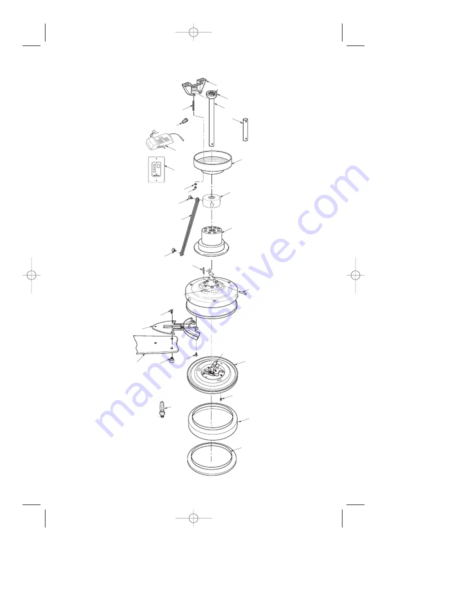
Repair Parts
3
2
1
5
4
26
14
15
6
7
17
16
9
23
11
28
27
8
25
13
10
20
19
22
24
21
12
FAN OFF
LOW
MED
HI
LIGHT
BP7375 Highpointe 12/9/08 11:08 AM Page 18
Page 1: ...E INSTRUCTIONS Net Weight 22 1 Lbs HIGHPOINTE Ceiling Fan Owner s Manual Model Numbers CF205BS00 Brushed Nickel Finish with Opal Matte Glass and Dark Mahogany Blades CF205GES00 Golden Espresso with Sandstone Glass and Chocolate Blades BP7375 Highpointe 12 9 08 11 08 AM Page 1 ...
Page 2: ...r a 9 foot ceiling The 6 downrod supplied must be used for an 8 foot ceiling 5 The fan must be mounted with the fan blades at least 7 feet from the floor to prevent accidental contact with the fan blades 6 Follow the recommended instructions for the proper method of wiring your ceiling fan If you do not know enough about electrical wiring have your fan installed by a licensed electrician CAUTION T...
Page 3: ...njury or property damage WARNING a Fan motor housing assembly b One ceiling cover c One coupling cover d Three fan blades e Three blade flanges f Nine decorative blade nuts bagged g One hanger bracket h One hanger ball 12 downrod assembly i One 6 downrod j One rod support assembly k Three decorative rod assemblies l Six decorative rod assembly screws bagged m One light kit plate n One lower glass ...
Page 4: ...CODE SWITCH SW102 WALL CONTROL Figure 1 Your SW102 Fan Light Wall Control and Receiver have code switches which must be set in one of 16 possible code combi nations The four levers numbered 1 2 3 and 4 on the switches are factory set in the ON up position Change the switch settings as follows 1 Slide the four switch levers in the wall control to your choice of ON up or down positions Use a ball po...
Page 5: ...escribed in these instructions should be done or approved by a licensed electrician WARNING If your fan is to replace an existing ceiling light fixture turn electricity off at the main fuse box at this time and remove the exist ing light fixture U L Model No CF205 12V BATTERY WALL CONTROL COVER SW102 WALL CONTROL HI HI MED MED LOW LOW FAN OFF LIGHT Figure 2 3 Install the wall control onto the outl...
Page 6: ...ely while interlocking the flange assemblies as you rotate the hub Figure 5 Your ceiling fan can be assembled with the light kit and glass or without the light kit and glass To assemble without the light kit and glass you will use the no light cover plate In order to use the no light cover plate the light sockets will need to be removed from the light kit plate FAN BLADE DECORATIVE BLADE NUTS 3 BL...
Page 7: ...r the inside of the motor coupling Then separate untwist and unkink the three 80 motor leads Route the motor lead wires through the downrod Align the clevis pin holes in the downrod with the holes in the motor coupling Install the clevis pin and secure with the hairpin clip Figure 9 The clevis pin must go through the holes in the motor cou pling and the holes in the downrod Be sure to push the str...
Page 8: ...ion while tightening all six decorative rod screws securely DECORATIVE ROD ASSEMBLY DECORATIVE ROD SCREW Figure 11 8 U L Model No CF205 10 Make sure the grommet Is properly installed in the coupling cover then slide the coupling cover over the downrod until it rests on the motor housing Figure 10 NOTE If you installed the 6 downrod the three decorative rod assemblies and the rod support assembly w...
Page 9: ...F205 How to Hang Your Ceiling Fan The fan must be hung with at least 7 of clearance from floor to blades Figure 14 WARNING The outlet box and joist must be securely mounted and capable of supporting at least 50 lbs Use only a U L outlet box listed as Acceptable for Fan Support WARNING To reduce the risk of fire electric shock or personal injury mount fan to outlet box marked Acceptable for Fan Sup...
Page 10: ...n against possible electrical shock WARNING If you feel that you do not have enough electrical wiring knowledge or experi ence have your fan installed by a licensed electrician 10 CAUTION To reduce the risk of electri cal shock disconnect the electrical supply circuit before installing the fan light kit or receiver 2 Carefully lift the fan and seat the hang er ball downrod assembly on the hang er ...
Page 11: ...OM HANGER BRACKET RECEIVER RED WIRE RECEIVER WHITE WIRE FAN WHITE WIRE FAN BLACK WIRE ANTENNA AC IN N AC IN L FO R LI G HT TO M O TO R N RECEIVER BLUE WIRE RECEIVER BLACK WIRE RECEIVER WHITE WIRE SUPPLY WHITE WIRE NEUTRAL SUPPLY BLACK WIRE HOT GROUND WIRE GREEN GROUND WIRE FROM HANGER BALL FAN BLUE WIRE 1 1 4 THREADED STUD 2 T O M O T O R L Figure 17 11 U L Model No CF205 STANDARD ON OFF WALL SWIT...
Page 12: ...p into the outlet box while inserting the receiv er fully into the hanger bracket Position the antenna wire on top of the receiver 4 Screw the two 1 1 4 threaded studs supplied into the tapped holes in the hanger bracket Figure 19 5 Lift the ceiling cover up to the threaded studs and turn until the studs protrude through the holes in the ceiling cover Figure 19 6 Secure the ceiling cover in place ...
Page 13: ... wire of the light kit plate from the black wire of the fan motor housing assembly Disconnect the white wire of the light kit plate from the white wire of the fan motor housing assembly Figure 22 LIGHT KIT PLATE CUT LIGHT SOCKET WIRES CUT LIGHT SOCKET WIRES Figure 22 REASSEMBLE LIGHT KIT PLATE REASSEMBLE MOTOR SCREW 3 REMOVE SOCKET PLATE SCREWS 2 per plate REMOVE SOCKET SOCKET PLATE 2 Figure 23 Tu...
Page 14: ...he cover plate onto the fan motor housing aligning the three flat areas on the top flange of the cover plate with the three pins on the inside of the fan motor housing Figure 24 Then turn the cover plate clockwise until it stops turning 6 Your cover plate is now installed To avoid possible fire or shock make sure that the electrical wires are com pletely tucked inside the lower assembly and not pi...
Page 15: ...PORTANT CARE INSTRUCTIONS for your Ceiling Fan Periodic cleaning of your new ceiling fan is the only maintenance that is needed When cleaning use only a soft brush or lint free cloth to avoid scratching the finish Abrasive cleaning agents are not required and should be avoided to prevent damage to finish Accessories 1 Downrod Extension Kits see store or catalog 2 Ceiling Fan Controls see store or ...
Page 16: ...rect the interference by one or more of the following measures Reorient or relocate the receiving antenna Increase the separation between the equipment and receiver Connect the equipment into an outlet on a circuit different from that to which the receiver is connected Consult the dealer or an experienced radio TV technician for help This equipment has been certified to comply with the limits for ...
Page 17: ... each other or against the interior wall of the switch housing WARNING Make sure main power is turned off 4 Screws holding blades to 4 Tighten screws securely flanges are loose 5 Loose screws in motor housing 5 Check to make sure all screws in motor housing are snug not over tight 3 Fan wobbles 1 Setscrew in motor coupling is 1 Raise coupling cover and tighten excessively not tightened securely se...
Page 18: ...18 U L Model No CF205 Repair Parts 3 2 1 5 4 26 14 15 6 7 17 17 16 18 9 23 11 28 27 8 25 13 10 20 19 22 24 21 22 12 FAN OFF LOW MED HI LIGHT BP7375 Highpointe 12 9 08 11 08 AM Page 18 ...
Page 19: ... Coupling 762708 BS 762708 GES 19 Blade Set full set for one fan 763601 763601 1 20 Flange Set full set for one fan 763597 BS 763597 GES 21 Harness Assembly Wiring 763595 763595 22 Fitter Assembly Light 763603 BS 763603 GES 23 Glass Lower 763605 763605 1 24 Cover Plate 763609 BS 763609 GES 25 Bulb Halogen 50 watt Mini candelabra Base 26 Downrod 6 761631 32 761631 44 27 Transmitter Wall Control SW1...
Page 20: ... 1 800 654 3545 for the address of the nearest authorized service center You will be responsible for all insurance freight or other transportation charges to our factory or authorized service center Your Emerson Air Comfort Ceiling Fan should be properly packed to avoid damage in transit since we will not be responsible for any such damage What Is Not Covered The glass globes and light bulbs of yo...