PACMotion™ Rotary Servo Motors Installation and User Manual
Section 3
GFK-3169C
Mar 2021
Mechanical Installation
17
Section 3:
Mechanical Installation
Note: Dimension drawings can be found in chapter "Dimension Drawings".
3.1
Important Notes
Note: Only qualified staff with knowledge of mechanical engineering are permitted to assemble the
motor.
Protect the motor from unacceptable stresses. During transport and handling no components must be
damaged.
The site must be free of conductive and aggressive material. For V3-mounting (shaft end upwards), make
sure that no liquids can enter the bearings. If an encapsulated assembly is required, please consult
Emerson beforehand.
Ensure an unhindered ventilation of the motors and observe the permissible ambient and flange
temperatures. For ambient temperatures above 40°C please consult our applications department
beforehand. Ensure that there is adequate heat transfer in the surroundings and the motor flange.
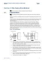
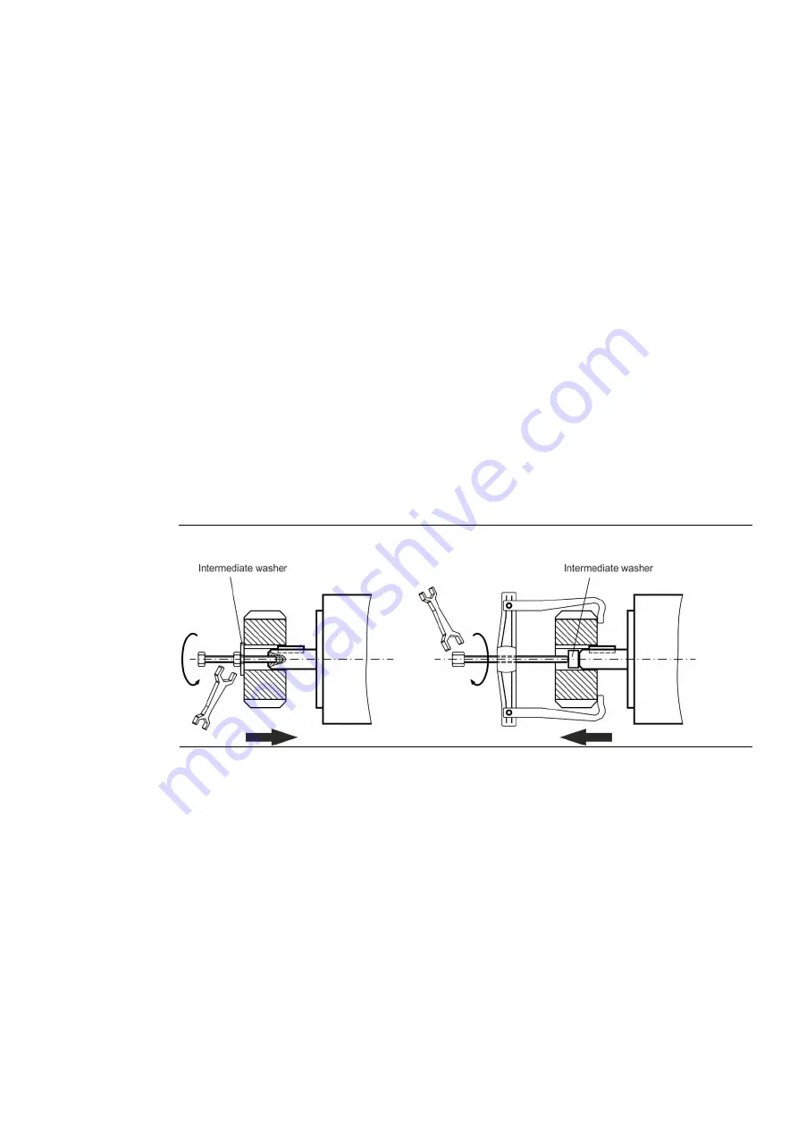
Motor flange and shaft are especially vulnerable during storage and assembly - so avoid brute force. It is
important to use the locking thread which is provided to tighten up coup- lings, gear wheels or pulley
wheels and warm up the drive components, where possible. Blows or the use of force will lead to damage
to the bearings and the shaft.
Figure 5: Intermediate Washer
•
Wherever possible, use only backlash-free, frictionally-locking collets or couplings. Ensure
correct alignment of the couplings. A displacement will cause unacceptable vibration and the
destruction of the bearings and the coupling.
•
In all cases, do not create a mechanically constrained motor shaft mounting by using a rigid
coupling with additional external bearings (e.g. in a gearbox).
•
Take note of the no. of motor poles and the no. of resolver poles (if applicable), and ensure that
the correct setting is made in the servo amplifier which is used. An incorrect setting can lead to
the destruction of the motor, especially with small motors.
•
Avoid axial loads on the motor shaft, as far as possible. Axial loading significantly shortens the life
of the motor.
•
Check the compliance to the permitted radial and axial forces F
R
and F
A
. When you use a toothed
belt drive, the minimal permitted diameter of the pinion
•
e.g. follows from the equation: d
min
≥ (M
0
/F
R
)*2


