


DVC6200f Digital Valve Controller
November 2010
146
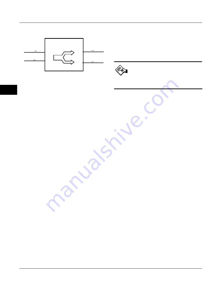
RCAS
IN
CAS
IN
OS
OUT
1
OUT
2
Figure 4-15. Output Splitter (OS) Function Block
Output Splitter (OS) Function Block
Overview
The Output Splitter block provides the capability to
drive two control outputs from a single input. Each
output is a linear function of some portion of the input.
Back calculation support is provided using the same
linear function in reverse. Cascade initialization is
supported by a decision table for combinations of input
and output conditions.
This block is normally used in split ranging or
sequencing of multiple valve applications. A typical
split range application has both valves closed when
the splitter input is 50%. One valve opens fully as the
input drops to 0%. The other valve opens as the input
rises above 50%.
A typical sequencing application has both valves
closed at 0% input. One valve fully opens as the input
rises to 50% and the other stays shut. The second
valve opens as the input rises above 50%, and the
first valve may remain open or shut off quickly.
Because this block is in the control path, it is able to
pass limit and cascade initialization information back
to the upstream block. Table 4-48 lists the OS block
parameters and their descriptions, units of measure,
and index numbers. Figures 4-16 and 4-17 illustrate
the internal components of the OS function block.
Modes
The Output Splitter function block supports the
following actual modes:
Out of Service (OOS)—The block is not
processed. FIELD_VAL and PV are not updated and
the OUT status is set to Bad: Out of Service. The
BLOCK_ERR parameter shows Out of Service. In this
mode, you can make changes to all configured
parameters.
By using permitted mode the target mode of a block
may be restricted to one or more of the following
modes: Cas, Auto or OOS.
Note
The output splitter function block must
be in Auto for the mode to go to CAS.
Initialization Manual (IMan)—The output path
is not complete (for example, the cascade
−
to
−
slave
path might not be open). In IMan mode, OUT tracks
BKCAL_IN, which allows for bumpless transfer of
control.
Automatic (Auto)—The block outputs (OUT_1
and OUT_2) reflect the target operating point specified
by the setpoint (SP) parameter.
Cascade (Cas)—The SP parameter is set by
another function block through a connection to
CAS_IN. The SP value is used to set the OUT
parameters automatically. This is the most frequently
used mode in this block.
The block’s normal mode is Cascade (Cas). You can
isolate the block for testing by using Automatic (Auto)
mode and adjusting the setpoint.
When a block attached to an output requests
initialization, one of the following actions might occur:
When the other output is not in Cas mode, the
block attached to the input is initialized.
When the other output is in Cas mode, this
output returns to the value calculated from its slope in
a specified time period.
Status Handling
Sub-status value received at CAS_IN [14] is passed to
both outputs, except for those used in the cascade
handshake. An IFS goes to both outputs. The status
option IFS if Bad CAS_IN is available.
If the Status Option to Propagate failure is set, the
block propagates device failure only if both BKCAL_IN
show failed status. Otherwise the upstream cascade
would be broken by a failure at either output.
4
Summary of Contents for FIELDVUE DVC6200f
Page 42: ...DVC6200f Digital Valve Controller November 2010 30 4 ...
Page 60: ...DVC6200f Digital Valve Controller November 2010 48 4 ...
Page 108: ...DVC6200f Digital Valve Controller November 2010 96 4 ...
Page 122: ...DVC6200f Digital Valve Controller November 2010 110 4 ...
Page 188: ...DVC6200f Digital Valve Controller November 2010 176 4 ...
Page 200: ...DVC6200f Digital Valve Controller November 2010 188 4 ...
Page 216: ...DVC6200f Digital Valve Controller November 2010 204 5 ...
Page 250: ...DVC6200f Digital Valve Controller November 2010 238 8 ...
Page 254: ...DVC6200f Digital Valve Controller November 2010 242 A ...
Page 284: ...DVC6200f Digital Valve Controller November 2010 272 D ...
Page 290: ...DVC6200f Digital Valve Controller November 2010 278 E ...
Page 308: ...DVC6200f Digital Valve Controller November 2010 296 F ...
Page 312: ...DVC6200f Digital Valve Controller September 2010 300 Notes G Glossary ...
Page 324: ...DVC6200f Digital Valve Controller November 2010 312 F Index ...


