


DVC6200f Digital Valve Controller
November 2010
100
B2717 / IL
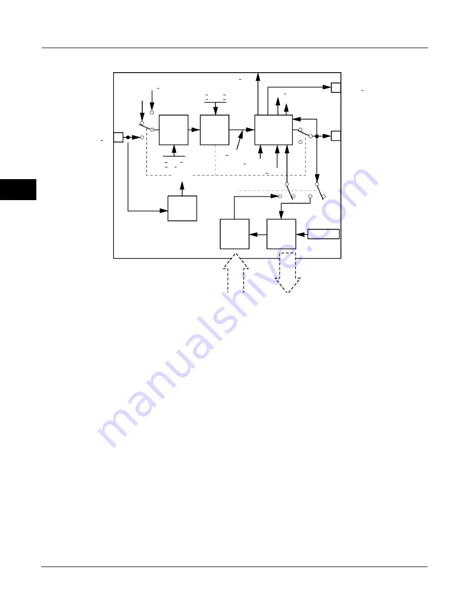
CAS IN
Position
Feedback
Analog
Output
Access
Analog
Output
Access
Analog
Input
Shed
Mode
SP
HI/LO
Limit
SP
Rate
Limit
Convert
and Status
Calculation
BKCAL OUT
OUT
RCAS OUT
RCAS IN
SP RATE DN
SP RATE UP
SP WRK
PV SCALE
IO OPTS
Operator
Setpoint
READ BACK
PV
SP LOW LIM
SP HI LIM
CHANNEL
MODE
Figure 4-7. Analog Output Function Block Schematic
Auto—On failure of a remote cascade connection, the
block sets the target mode to Auto, if permitted.
Man—On failure of remote cascade connection, the
block sets the target mode to Man, if permitted.
The user may configure SHED_OPT [27] so that it
calls for a target mode that is not permitted. When
doing this, the mode logic uses the following rules as
applied by the remote logic:
Shed logic never results in a non-permitted target
mode.
Shed logic never attempts to attain an actual
mode of Auto or Cas if that mode is not permitted.
Status Handling
Output or readback fault detection is reflected in the
status of PV [7], OUT [9], and BKCAL_OUT [25]. A
limited SP [8] condition is reflected in the
BKCAL_OUT [25] status. When simulation is enabled
through the SIMULATE [10] attribute, you can set the
value and status for PV [7] and READBACK [16].
When the block is in Cas mode and the CAS_IN [17]
input goes bad, the block sheds mode to the next
permitted mode.
Setting the Output
To set the output for the AO block, you must first set
the mode to define the manner in which the block
determines its setpoint. In Manual mode the value of
the output attribute (OUT [9]) must be set manually by
the user, and is independent of the setpoint. In
Automatic mode, OUT [9] is set automatically based
on the value specified by the set point (SP [8]) in
engineering units and the I/O Options attribute.
In
addition, you can limit the SP [8] value and the rate at
which a change in the SP [8] is passed to OUT [9].
In Cascade mode, the cascade input connection
(CAS_IN [17]) is used to update the SP [8]. The back
calculation output (BKCAL_OUT [25]) is wired to the
back calculation input (BKCAL_IN [27]) of the
upstream block that provides CAS_IN [17]. This
provides bumpless transfer on mode changes and
windup protection in the upstream block.
4
Summary of Contents for FIELDVUE DVC6200f
Page 42: ...DVC6200f Digital Valve Controller November 2010 30 4 ...
Page 60: ...DVC6200f Digital Valve Controller November 2010 48 4 ...
Page 108: ...DVC6200f Digital Valve Controller November 2010 96 4 ...
Page 122: ...DVC6200f Digital Valve Controller November 2010 110 4 ...
Page 188: ...DVC6200f Digital Valve Controller November 2010 176 4 ...
Page 200: ...DVC6200f Digital Valve Controller November 2010 188 4 ...
Page 216: ...DVC6200f Digital Valve Controller November 2010 204 5 ...
Page 250: ...DVC6200f Digital Valve Controller November 2010 238 8 ...
Page 254: ...DVC6200f Digital Valve Controller November 2010 242 A ...
Page 284: ...DVC6200f Digital Valve Controller November 2010 272 D ...
Page 290: ...DVC6200f Digital Valve Controller November 2010 278 E ...
Page 308: ...DVC6200f Digital Valve Controller November 2010 296 F ...
Page 312: ...DVC6200f Digital Valve Controller September 2010 300 Notes G Glossary ...
Page 324: ...DVC6200f Digital Valve Controller November 2010 312 F Index ...


