background image

Emerson FB3000 RTU Instruction Manual  
D301851X012  

May 2022 

72 

Service and Troubleshooting 

5.5


Removing/Replacing the CPU Module (3CPU16)  


DANGER


Ensure the RTU is in a non-hazardous area. Never open the enclosure in a hazardous 
area.   


DANGER


EXPLOSION HAZARD: Ensure the area in which you perform this operation is non-
hazardous. Performing this operation in a hazardous area could result in an explosion.  


DANGER


Switch the process this RTU controls over to whatever manual/backup system you 
have.  


 CAUTION


Backup data before you begin because replacing the CPU module may result in loss of 
configuration data, alarms, events, and history.  

 
1.


Backup data in the CPU (See


Section 5.9 

and 

Section 5.10

2.


Remove power from the FB3000. 

3.


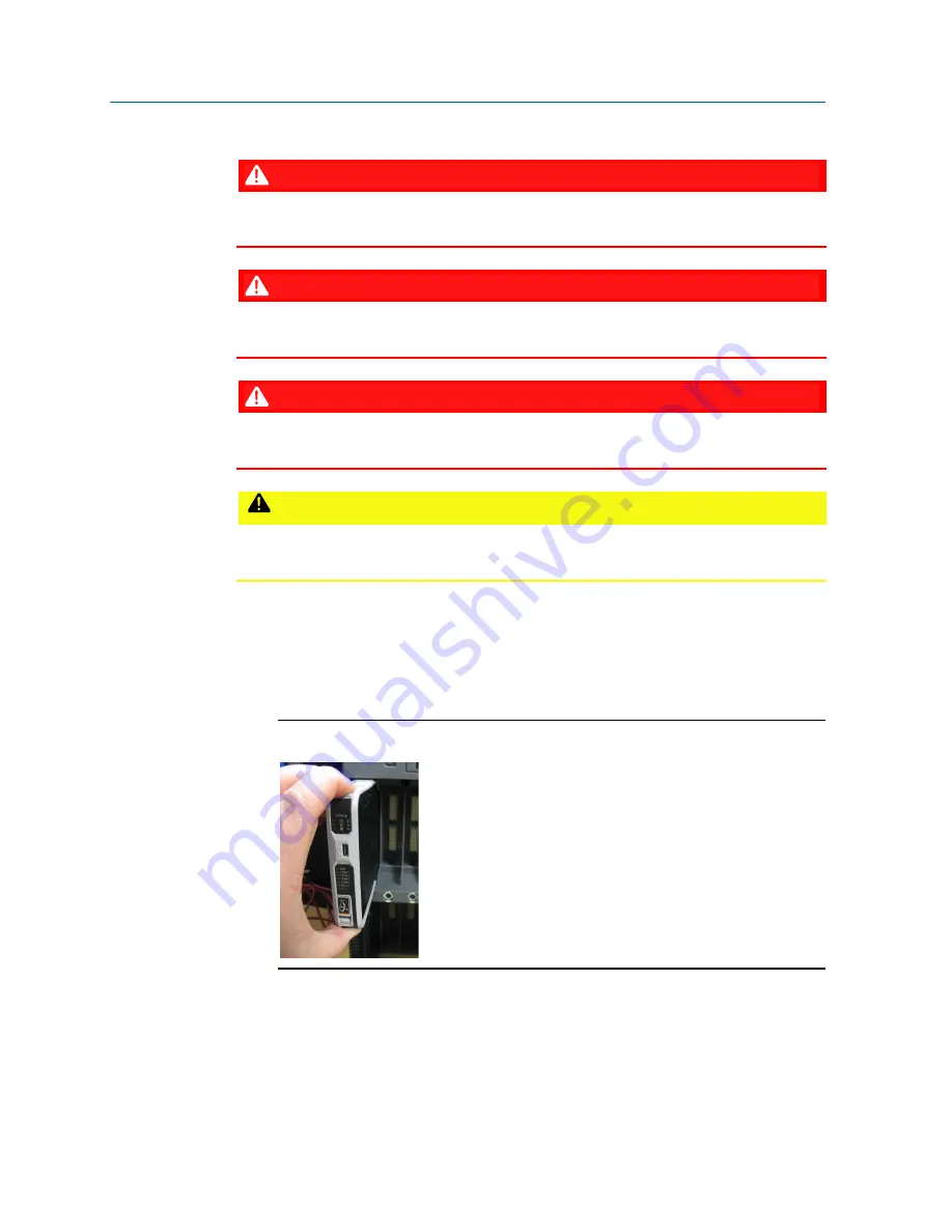
Depress the orange tabs at the top and bottom of the CPU module to release the 
module and slide it straight out of the slot. 

Figure 5-7: Removing the CPU Module   


Summary of Contents for FB3000

Page 1: ...Emerson FB3000 RTU Instruction Manual D301851X012 May 2022 Remote Automation Solutions Emerson FB3000 Remote Terminal Unit RTU Instruction Manual ...

Page 2: ... ground mechanical or pneumatic instruments that include electrically operated devices such as lights switches relays alarms or chart drives The FB3000 includes a chassis ground lug Unless specifically noted the chassis ground is isolated from ground terminals on individual modules installed in the device to prevent noise The chassis ground lug provides a path to earth ground for electrical safety...

Page 3: ...PU Personality Module Assembly 400225 01 0 510007 01 0 3CPUSG FB3000 8 Slot DIN Rail Assembly 510001 01 0 3DIN08 FB3000 12 Mixed I O 12MIO Module Assembly 510006 01 0 400226 01 0 3MIX12 FB3000 12 Mixed I O 12MIO Personality Module Assembly 510076 01 0 3MSG12 FB3000 I O CPU Scanner Module 510121 01 0 3IOCPU FB3000 4 Channel HART I O Module 510114 01 0 3HRT04 FB3000 4 Channel HART I O Personality Mo...

Page 4: ...or 30 minutes Locations The Emerson FB3000 Remote Terminal Unit RTU is listed by the Canadian Standards Association CSA as suitable for use in Class I Division 2 Groups A B C and D hazardous locations when installed in a suitably rated enclosure and in Class I Zone 2 AEX Ex ec IIC Gc hazardous locations when installed in an IP54 enclosure per requirements of standards CSA UL 60079 0 and CSA UL 600...

Page 5: ...l mounting as the method of installation for the extended backplane configuration use DIN rail end brackets at the two ends of the extended backplane to prevent side movements of the equipment on the DIN rail Refer to the Emerson FB3000 RTU Instruction Manual D301851X012 for details CSA evaluates this equipment according to the following standards CAN CSA C22 2 No 0 10 August 2011 General requirem...

Page 6: ...EXPLOSION HAZARD CONNECT OR DISCONNECT ONLY IN A NON HAZARDOUS AREA WARNING EXPLOSION HAZARD DO NOT REMOVE OR REPLACE WHILE CIRCUIT IS LIVE UNLESS THE AREA IS FREE OF IGNITABLE CONCENTRATIONS WARNING EXPLOSION HAZARD DO NOT REMOVE OR REPLACE FUSE WHEN ENERGIZED DANGER EXPLOSION HAZARD BATTERIES MUST ONLY BE CHANGED IN AN AREA FREE OF IGNITABLE CONCENTRATIONS WARNING DO NOT USE THE USB CONNECTOR UN...

Page 7: ...FB3000 CSA Approval Information CD9411L Issued March 11 2021 CSA 5 ...

Page 8: ......

Page 9: ...equired Tools 7 2 3 Site Considerations 8 Connecting Extension Chassis 9 2 4 General Wiring Guidelines 10 2 5 Grounding 11 Chassis Ground Lug 11 Internal System Bus Ground 12 Isolated Ground on 3MIX12 Module 13 24V Loop Ground on 3MIX12 Module 14 2 6 Mounting the Chassis 15 Panel or Wall Mounting the Aluminum Enclosure 16 2 7 Removing Battery Saver Tabs 18 2 8 Connecting Power 18 Connecting Extern...

Page 10: ...oint to Point Mode 49 3 6 1 2 Multi Drop Mode 50 3 6 1 3 Analog Input Mode HART Communication Disabled 52 3 6 1 4 Analog Output Mode HART Communication Disabled 53 3 6 2 Software Configuration 54 4 1 Powering Up Powering Down the Device 57 4 2 Establishing Communications 57 4 2 1 Communicating with the SCADA Host 57 4 2 2 Communicating with a Laptop Using a Serial Port 58 4 2 3 Communicating with ...

Page 11: ...851X012 May 2022 Contents v 5 6 Removing Replacing an I O Module 3MIX12 73 5 7 Removing Replacing a Personality Module 75 5 8 Upgrading System Firmware 76 5 9 Backing Up Historical Data and Your Configuration 77 5 10 Backing Up Your Solution 78 ...

Page 12: ......

Page 13: ...can also purchase the FB3000 as an I O only device FBxRemote I O where control runs in a separate host FB3000 RTU This manual describes how to install and configure the FB3000 hardware For information on using the FBxConnect configuration software see the online help that accompanies FBxConnect Figure 1 1 FB3000 RTU 1 Chassis 2 Chassis Ground Lug 3 Power Supply Modules 2 4 Ethernet Ports on CPU mo...

Page 14: ... all precautionary signs posted on the equipment Failure to do so may result in injury to personnel or cause damage to the equipment CAUTION MAY CAUSE INJURY TO PERSONNEL OR DAMAGE EQUIPMENT Observed all precautionary signs posted on the equipment Failure to do so may result in injury to personnel or cause damage to the equipment SAFETY FIRST General instructions and safety reminders 1 2 Features ...

Page 15: ...fully populated with modules you can fill the empty slots with slot covers to protect the connectors from dust These are installed removed using the same screws used for personality modules If you require more than seven I O slots you can optionally purchase one two or three extension chassis to attach to the base chassis allowing an additional 8 16 or 24 I O slots 1 4 Central Processing Unit CPU ...

Page 16: ...I O Other than slot 1 in the base chassis which is reserved for the CPU any slot can contain an I O module Each 12 channel Mixed I O module labelled 3MIX12 supports the following inputs outputs Eight 8 input channels that you can individually configure using FBxConnect as analog inputs AI digital inputs DI or pulse inputs PI AIs are software selectable as either 1VDC to 5VDC or 4 mA to 20 mA Two 2...

Page 17: ...sockets The Micro A B USB port resides on the front of the CPU module and supports DNP3 communication The serial ports allow communication using DNP3 Modbus slave and Modbus master protocols Table 1 4 Serial Ports Port Type Use COM1 Serial communication Software selectable for RS 232 or RS 485 operation 4 wire RS 232 or RS 485 communication to host or other devices 4 wire used with external radio ...

Page 18: ...eeded Update system firmware Optional FBxDesigner programming software lets you create custom applications for the RTU using any of the five IEC61131 languages 1 9 RoHS Compliance RoHS2 RoHS 2 EU Directive 2011 65 EU China RoHS 1 10 Secure Gateway For enhanced data security when using an IP Ethernet connection or a serial connection into an IP terminal server Emerson Remote Automation Solutions re...

Page 19: ...certifications for Class I Division 2 Groups A B C D non incendive and non hazardous locations only For other world areas the FB3000 has ATEX and IEC Ex certifications for Ex ec Zone 2 non sparking installations and non hazardous locations only All certifications are listed on the data plate located on the top of the device Refer to the CSA Approval Information document CD9411 for special informat...

Page 20: ...al Magnets Battery removal Non metallic tool Battery removal Laptop PC running Field Tools with FBxConnect configuration software Software configuration 2 3 Site Considerations The RTU must reside in an accessible location for configuration and service Refer to the dimensional drawings for information on the space required Figure 2 1 FB3000 Dimensions 8 Slot with without DIN Rail mounting plate as...

Page 21: ...ERSONNEL OR DAMAGE EQUIPMENT When mounting an FB3000 with one or more extension chassis in an enclosure ensure that you mount the racks in a left to right horizontal direction wall mount on DIN rails inside the end user system enclosure to allow for adequate heat dissipation Never mount the racks in a vertical stacked direction Notes If using multiple chassis the length dimension increases by appr...

Page 22: ...tween 24 and 12 AWG depending on the connector or terminal block and the usage Use 28 to 16 AWG wires on the 20 pin I O connectors use 20 to 12 AWG wires on the power connection CAUTION All wires must be rated for a temperature of 90o C or higher CAUTION Wires used for power must have a wire gauge between 20 and 12 AWG When making a connection insert the bare end of the wire approx 1 4 max into th...

Page 23: ... the terminal block out of its socket 2 5 Grounding There are four separate and distinct ground references within the FB3000 architecture The chassis ground lug also known as Protective Earth or PE internal system bus ground isolated ground and the 24V loop ground Chassis Ground Lug The RTU includes a chassis ground lug to the left of the power supply modules In CSA documents this may be called th...

Page 24: ...G 0000 cable installed vertically or horizontally Run the ground wire so that any routing bend in the cable has a minimum radius of 30 48 cm 12 inches below ground and 20 32 cm 8 inches above ground Note If your installation includes multiple chassis you must individually ground each chassis For more information on grounding or if your installation uses cathodic protection refer to Site Considerat...

Page 25: ... TB1 ISOGND provides a low noise return ground for analog inputs and outputs It is completely isolated from the other three ground systems You can optionally enable grounding for one or both digital outputs on the 3MIX12 through individual settings for each DO in FBxConnect When enabled digital output s are internally connected to ISOGND Figure 2 5 Isolated Ground Terminal Locations Highlighted in...

Page 26: ...llation 24V Loop Ground on 3MIX12 Module Pin 20 on TB1 of the 3MIX12 mixed I O module serves as the return side of the 24V loop power supply It is completely isolated from the other three ground systems Figure 2 6 Loop Power Ground Terminal Location Highlighted in Red ...

Page 27: ...p back into place If the RTU includes one or more extension chassis on the DIN rail ensure all chassis are pressed together tightly so that side connectors between chassis are fully engaged Install DIN rail clamps brackets at both ends of the assembly to ensure side connectors remain fully engaged Figure 2 8 Locations for Installing DIN rail clamps at each end of extension chassis assembly 1 DIN r...

Page 28: ... you can insert screws to mount the RTU to a panel or wall You also need to remove I O and personality modules to show the holes on the other side 1 Remove I O modules in slots 2 3 6 and 7 2 Remove personality modules in slots 2 and 7 3 Use a 2 Phillips head screwdriver to remove the four screws that secure the mounting plate Figure 2 9 Panel Wall Mounting Screw Locations 4 Slide the mounting plat...

Page 29: ...2 Installation 17 5 Insert longer screws screw length depends on the wall panel in the holes shown in Figure 2 9 to mount the device to a wall or panel The shafts of the screws push through the locations shown in Figure 2 11 Figure 2 11 Screw holes From Back ...

Page 30: ...E label and pull the tab straight out Figure 2 12 Battery Saver Tab 2 8 Connecting Power Power comes from an external power source The device supports both 12V and 24V power supplies It accepts DC voltage from 10 5 to 30V the amount of power required varies depending upon the options used The RTU does not include an internal charger or other infrastructure to support a battery or battery solar pow...

Page 31: ... Configuration Power 12V Power 24V 1 3CPU16 3CPUSG Only 4x 4088s FBxConnect on USB 1 second IO scan rate COM 1 2 ETH 1 2 disabled 1 464W 1 608W 2 CFG 1 plus 3MIX12 3MSG12 in slot 2 AIDIPI configured as DI with 66uA pull up AOs Loop Supply disabled 2 448W 2 784W 3 CFG 2 plus 50ms IO scan rate 2 556W 3 072W 4 CFG 3 plus COM1 COM2 ETH1 enabled COM1 COM2 ETH1 USB running FBxConnect 50ms IO scan rate 4...

Page 32: ...op power connections you must power the other 11 through a separate external power supply Similarly if you have a 24V installation and you install the maximum of 31 mixed I O modules the RTU s loop power can only power 21 of them you must power the remaining 10 through a separate external supply Figure 2 14 External Power Connections 1 Input power from external power supply power for RTU 2 Loop po...

Page 33: ...Installation 21 2 9 Removing the I O Cover Apply pressure on both sides of the cover where it meets the chassis and pull the cover off Figure 2 15 Removing the I O Cover To replace the cover line it up with the mating slots on the chassis and press the cover on ...

Page 34: ...top running FBxConnect software or to other devices Table 2 4 COM Terminal Block Pin RS 232 4 Wire RS 485 2 Wire RS 485 COM1 1 TXD1 TX1 TX1 2 RTS1 TX1 TX1 3 RXD1 RX1 4 CTS1 RX1 5 GND GND GND COM2 6 TXD2 TX2 TX2 7 RTS2 TX2 TX2 8 RXD2 RX2 9 CTS2 RX2 10 GND GND GND COM3 11 T3 Isolated RS 485 only 12 T3 ISO GND 13 TX RX 3 14 TX RX3 COM4 15 T4 Isolated RS 485 only 16 T4 ISO GND 17 TX RX4 18 TX RX4 19 2...

Page 35: ... RS 232 RS 485 4 wire or RS 485 2 wire communications When connecting COM1 to another device using RS 232 use a cable with configurations as shown in Figure 2 17 Figure 2 17 COM1 Configured as RS 232 1 RS 232 port on device 2 Connect cable shields to suitable Instrument Earth connection point When connecting COM1 to another device using RS 485 4 wire use a cable with configurations as shown in Fig...

Page 36: ...B3000 RTU Instruction Manual D301851X012 May 2022 24 Installation Figure 2 18 COM1 Configured as RS 485 4 wire 1 RS 485 4 wire port on device 2 Connect cable shields to suitable Instrument Earth connection point ...

Page 37: ...e a cable with configurations as shown in Figure 2 19 Figure 2 19 COM1 Configured as RS 485 2 wire 1 RS 485 2 wire port on device 2 Connect cable shields to suitable Instrument Earth connection point Regardless of the interface standard RS 232 RS 485 4 wire or RS 485 2 wire you must use FBxConnect to configure the port for proper usage ...

Page 38: ... the COM2 port as RS 232 RS 485 4 wire or RS 485 2 wire communications When connecting COM2 to an RS 232 port on another device a PC or another controller RTU use a cable with configurations as shown in Figure 2 20 Figure 2 20 COM2 Configured as RS 232 1 RS 232 port on device 2 Connect cable shields to suitable Instrument Earth connection point ...

Page 39: ...on 27 When connecting COM2 to an RS 485 4 wire port on another device use a cable with configurations as shown in Figure 2 21 Figure 2 21 COM2 Configured as RS 485 4 wire 1 RS 485 4 wire port on device 2 Connect cable shields to suitable Instrument Earth connection point ...

Page 40: ... use a cable with configurations as shown in Figure 2 22 Figure 2 22 COM2 Configured as RS 485 2 wire 1 RS 485 2 wire port on device 2 Connect cable shields to suitable Instrument Earth connection point Regardless of the interface standard RS 232 RS 485 4 wire or RS 485 2 wire you must use FBxConnect to configure the port for proper usage ...

Page 41: ...ng COM3 to an RS 485 port on another device such as a Rosemount 4088B transmitter use a cable with configurations as shown in Figure 2 23 Figure 2 23 COM3 Configured as RS 485 2 wire and Connected to a 4088B Transmitter 1 Enable AC termination using switches 2 RS 485 bus twisted pair required 3 Connect cable shields to suitable Instrument Earth connection point ...

Page 42: ...s on last multi dropped 4088B transmitter 2 RS 485 bus twisted pair required 3 Up to ten 4088B transmitters allowed per port FB3000 only provides power for a maximum of four transmitters Any other transmitters require an external power supply When communicating with more than six 4088Bs at 9600 baud update times exceed once a second 4 Connect cable shields to suitable Instrument Earth connection p...

Page 43: ...necting COM4 to an RS 485 port on another device such as a Rosemount 4088B transmitter use a cable with configurations as shown below Figure 2 25 COM4 Configured as RS 485 2 wire and Connected to a 4088B Transmitter 1 Enable AC termination using switches 2 RS 485 bus twisted pair required 3 Connect cable shields to suitable Instrument Earth connection point ...

Page 44: ...s on last multi dropped 4088B transmitter 2 RS 485 bus twisted pair required 3 Up to ten 4088B transmitters allowed per port FB3000 only provides power for a maximum of four transmitters Any other transmitters require an external power supply When communicating with more than six 4088Bs at 9600 baud update times exceed once a second 4 Connect cable shields to suitable Instrument Earth connection p...

Page 45: ...ector is compatible with either Micro A USB or Micro B USB plugs but is not compatible with Micro C plugs You can use the Micro A B USB port for DNP3 slave communications When configuring the USB port ignore baud rate and other settings simply choose the correct COM port and communicate as if using one of the serial ports Figure 2 27 Location of Ethernet Ports and Micro USB Port 1 Ethernet Port 1 ...

Page 46: ...Emerson FB3000 RTU Instruction Manual D301851X012 May 2022 34 Installation ...

Page 47: ...osion Hazard Do not remove or replace while circuit is live unless the area of free of ignitable concentrations The I O module is designated as 3MSG12 Table 3 1 Supported I O Modules Type Name Description 3MIX12 Mixed I O Module 8 channels you can individually configure as AI analog input DI digital input or PI pulse input 2 AO analog output channels 2 DO digital output channels 3HRT04 HART 4 HART...

Page 48: ...s Table 3 2 Analog Input Characteristics Type Number Supported Characteristics Analog Input AI Any of AIDIPI_01 through AIDIPI_08 can be individually configured as analog inputs 4 to 20 mA range or 1 to 5V selectable within FBxConnect Analog inputs share a common ground When you configure a channel as an AI it cannot be used as a DI or PI If current requirements are less than 200 mA 24V you can po...

Page 49: ...000 RTU Instruction Manual D301851X012 May 2022 I O Configuration and Wiring 37 Figure 3 1 Analog Input AI Wiring Using 1 5VDC or 4 20mA 1 External voltage source 2 External current source 3 Power Supply 30VDC Max ...

Page 50: ...d reference connect the 24V loop GND pin 20 externally to ISOGND in this case pin 10 Figure 3 2 Analog Input AI Wiring Using Loop Power 1 External current source 3 2 Analog Outputs The FB3000 s mixed I O modules includes two dedicated analog output channels with the following characteristics Table 3 3 Analog Output Characteristics Type Number Supported Characteristics Analog Output AO 2 dedicated ...

Page 51: ...ice AO_2 is configured for voltage output mode and is shown connected to an external voltage field device AO_1 has a dedicated ISO_GND pin 12 AO_2 has a dedicated ISO_GND pin 14 Figure 3 3 Analog Output AO Wiring Both AO channels are read back to check the health of the AO Current outputs with loads are verified to be within the operating range of the output Voltage outputs are verified to be with...

Page 52: ... Type Number Supported Characteristics Digital Input DI Any of AIDIPI_01 through AIDIPI_08 can be individually configured as digital inputs When a channel is configured as a DI it cannot be used as an AI or PI channel The range of digital inputs must remain within the span of 0VDC to 30VDC All digital inputs have 1V hysteresis applied to them switching levels are 2VDC for rising signals and 1VDC f...

Page 53: ...e 3 4 Digital Input DI Wiring internal pull up enabled 3 4 Digital Outputs The mixed I O modules of the FB3000 RTU include two dedicated digital output channels Notes When using a digital output to drive an inductive load such as a relay coil place a suppression diode across the load This protects the DO from the reverse Electro Motive Force EMF spike generated when the inductive load is switched ...

Page 54: ...racteristics Table 3 5 Digital Output Characteristics Type Number Supported Characteristics Digital Output DO 2 dedicated channels Contact closure by solid state relay Maximum current of 500mA at 31VDC Can be configured to fail at last output value or fail to a fault state You can enable an internal ground switch in FBxConnect connecting the low side to ground ...

Page 55: ...to use the internal ground switch that you enable within FBxConnect Current is limited to 50mA when using the low side switch Figure 3 5 Digital Output DO Wiring Low Side Internal Switch 1 Power Supply 30VDC Max 2 50 mA load max field device 3 Low side switch internal 4 Suppression diodes only one required Recommended placement is across inductive load When installing the diode ensure correct pola...

Page 56: ...e a digital output using the 24V internal loop power supply as a high side external switch This configuration uses the internal ground switch to connect the DOLO_1 side to ground Figure 3 6 Digital Output DO Wiring High Side Internal Switch with 24V Loop Supply 1 50 mA load max field device 2 High Side Switch INTERNAL ...

Page 57: ...3 7 shows how to wire a digital output as a dry contact closure Figure 3 7 Digital Output DO Wiring Dry Contact Closure 1 500 mA load max field device 2 30VDC Max Power Supply 3 DOHI_1 DOLO_1 configured as an external low side switch LSS 4 DOHI_2 DOLO_2 configured as an external high side switch HSS ...

Page 58: ...using the internal 24V loop supply The total current for all devices connected to a DO channel must not exceed 500 mA For example you could wire two devices in parallel one with 200 mA and another with 300 mA This figure shows a single device using 500 mA Figure 3 8 Digital Output DO Wiring Contact Closure using 24V Loop Supply 1 500 mA load max field device ...

Page 59: ...nput Characteristics Type Number Supported Characteristics Pulse Input PI Any of AIDIPI_01 through AIDIPI_08 can be individually configured as pulse inputs When a channel is configured as a PI it cannot be used as a DI or AI channel The range of pulse inputs must remain within the span of 0VDC to 30VDC All pulse inputs have 1V hysteresis applied to them switching levels are 2VDC for rising signals...

Page 60: ...3 6 HART Input Output Channels 3HRT04 The FB3000 RTU supports a HART Highway Addressable Remote Transducer module with four 4 channels This allows the FB3000 to communicate with external HART devices such as transmitters Insert the 3HRT04 module in any base chassis slot except slot 1 and insert its corresponding 3HTSG4 module below it Note The 3HRT04 module requires a chassis of Revision H or newe...

Page 61: ...mA analog current mode signal as well as the modulated HART digital signal riding on top of it Depending upon the HART device connected you can configure the channel as an AI which means the 250 ohm resistor is enabled or an AO which means the 250 ohm resistor is disabled Figure 3 10 shows how to wire all four HART channels in point to point mode In this case each HART channel only communicates to...

Page 62: ...put sink current of any 3HRT04 Module channel is 20mA and each device can draw 4mA a HART channel in multidrop mode supports a total of 5 HART devices With each of the 5 HART devices permitted to draw 4mA the sum of the currents is 20mA the maximum current Figure 3 11 shows how to wire a HART channel for multi drop mode Multi drop mode only supports inputs you cannot have multi drop outputs You ca...

Page 63: ... 2022 I O Configuration and Wiring 51 Figure 3 12 shows how to wire a HART channel for devices which do not use loop power but get power from an external power supply Figure 3 12 HART Wiring External Power Supply HD HART Device P External 24V Power Supply ...

Page 64: ...mm Mode to Disabled Figure 3 13 shows two examples for wiring a HART channel as a 4 20mA analog input In the figure an externally powered current loop transmitter connects to Channel 1 and a loop powerd current loop transmitter connects to Channel 4 Figure 3 13 Connecting 4mA to 20mA Analog Inputs to 3HRT04 Channel No HART communications 1 4 20mA Analog Signal Loop 2 Transducer 3 Power Supply 4 Se...

Page 65: ...e to Disabled Figure 3 14 shows two examples for wiring a HART channel as a 4 20mA analog output In the figure an externally powered current loop receiver connects to Channel 1 and a 24VDC loop supply powered current loop receiver connects to Channel 4 Figure 3 14 Connecting 4mA to 20mA Analog Outputs to 3HRT04 Channel No HART communications 1 4 20mA Analog Signal Loop 2 Transducer 3 Driver 4 Powe...

Page 66: ...nnel is an analog input click the Configuration tab to configure the AI 4 Specify whether this is a Primary or Secondary HART Master in the HART Master Type field 5 Enable the Termination Resistor if required 6 Choose the HART Comm Mode If you have a single HART device on the channel select Point to Point If multiple devices are multi dropped on the channel select Multidrop and specify the Number ...

Page 67: ...nual D301851X012 May 2022 I O Configuration and Wiring 55 9 Select the variables you want to poll from the device then click Save and Close the screen 10 If this channel uses multi drop repeat steps 8 and 9 for any unconfigured devices ...

Page 68: ...Emerson FB3000 RTU Instruction Manual D301851X012 May 2022 56 I O Configuration and Wiring ...

Page 69: ... laptop computer running FBxConnect 4 2 1 Communicating with the SCADA Host Communication to the RTU through a SCADA host computer requires configuration of the host computer software which varies depending upon whether you are using OpenEnterprise or another host software package Much of this configuration is beyond the scope of this topic but no matter which host you are using there are certain ...

Page 70: ...es and so on 4 2 2 Communicating with a Laptop Using a Serial Port Your laptop must have Field Tools software with FBxConnect software installed You must know a valid username password combination for the RTU WARNING Explosion Hazard Connect or disconnect only in a non hazardous area 1 Connect a cable between a serial port or serial USB adapter on your laptop and a serial port on the RTU See Chapt...

Page 71: ...n Ethernet port on your laptop and an Ethernet switch for your network 2 Connect a Category 5 shielded cable between your Ethernet switch and one of the two Ethernet ports on the RTU 3 Launch Field Tools and add an IP connection for the device then click Connect to start the FBxConnect software If you already have an existing saved IP connection for this device in Field Tools just double click on ...

Page 72: ...Emerson FB3000 RTU Instruction Manual D301851X012 May 2022 60 Operation ...

Page 73: ...everyone needs to know such as replacing batteries or installing a firmware upgrade Any replacement not covered in this chapter can only be performed at an Emerson authorized repair facility Important Only use batteries supplied with the RTU or sold by Emerson Remote Automation Solutions as spare parts for this RTU If you substitute a battery you obtain elsewhere you will void your hazardous locat...

Page 74: ...e Unit for Repairs Only certain field replacement procedures are allowed under warranty and hazardous location certification Other types of repairs cannot be performed in the field In those cases you must ship the unit to an Emerson authorized repair facility Contact Emerson Remote Automation Solutions for a return authorization number and instructions for where to ship the unit WARNING Internatio...

Page 75: ...ervice and Troubleshooting 63 5 2 Interpreting the Status LEDs Each of the modules in the RTU includes status light emitting diodes LEDs The meaning of each LED varies depending upon the color displayed or whether the LED flashes Figure 5 2 Status LED Locations ...

Page 76: ...e Return CPU to factory for repair Communication Status Flashing GREEN Communication in progress to I O module s RED One or more configured I O modules is not communicating with the CPU Flashing RED with USB LED also flashing GREEN and Module Status LED alternating RED and ORANGE CPU module is in wrong slot must be in slot 1 If this sequence occurs at a rate faster than approximately every half se...

Page 77: ...approximately every half second indicates a hardware failure Return CPU to factory for repair COM1 COM2 COM3 COM4 GREEN Receive on this port in progress RED Transmission on this port in progress ORANGE Receive and transmit in progress Off No transmissions active ISO T GREEN RS 485 communications enabled on COM3 or COM4 V GREEN Power applied to personality module Special Diagnostic LED Sequence A r...

Page 78: ...ion Board Status Flashing GREEN Firmware update in progress GREEN Personality module installed RED Personality module missing or mismatched type YELLOW Firmware incompatibility between CPU and I O module Review release notes and Board Info in FBxConnect and upgrade or downgrade firmware so CPU and I O module firmware revisions are compatible AI DI PI 1 through AI DI PI 8 Flashing GREEN PI present ...

Page 79: ...mmunication Status and Termination Status alternating flashing GREEN rapidly indicates power for the module has fallen to power trip point there is not enough power for the module I O held at current state Notes Any kind of failure takes priority over an alarm Any kind of alarm takes priority over override and normal Failure of an I O point is reported for one or more of these conditions Value abo...

Page 80: ...g GREEN Firmware update in progress GREEN Personality module installed RED Personality module missing or mismatched type YELLOW Firmware incompatibility between CPU and I O module Review release notes and Board Info in FBxConnect and upgrade or downgrade firmware so CPU and I O module firmware revisions are compatible HART1 HART2 HART3 HART4 GREEN Normal Flashing RED In alarm RED Failure Flashing ...

Page 81: ...of the power module and rotate the handle of the screwdriver upwards to rotate the module upwards Note Do not rotate the handle downwards as that may pop the cover off of the power module Figure 5 3 Removing Power Module 3 Now you can grasp the power module and pull it out Replacing a Power Module 1 Press the power module at an angle into the chassis with the tab at the rear end of the module goin...

Page 82: ...s third backup battery is 1250 hours You do not need to power down the unit to replace the SRAM backup batteries Important If the unit is ever powered down without the SRAM batteries installed SRAM data is lost this may include configuration data alarms events and history Always back up your data before you remove the SRAM batteries if you know that main power will also be off Important Replacemen...

Page 83: ... the writing on it must be facing downwards towards the RTU when the power module is installed 5 Reinstall the power module Battery in CPU Module 1 Remove the battery access door at the bottom of the CPU module and the door magnet will pull out the battery If this doesn t work use your own external magnet to pull out the battery Figure 5 5 Removing the SRAM Battery 2 Safely dispose of the old batt...

Page 84: ...s operation in a hazardous area could result in an explosion DANGER Switch the process this RTU controls over to whatever manual backup system you have CAUTION Backup data before you begin because replacing the CPU module may result in loss of configuration data alarms events and history 1 Backup data in the CPU See Section 5 9 and Section 5 10 2 Remove power from the FB3000 3 Depress the orange t...

Page 85: ...2 DANGER Ensure the RTU is in a non hazardous area Never open the enclosure in a hazardous area DANGER EXPLOSION HAZARD Ensure the area in which you perform this operation is non hazardous Performing this operation in a hazardous area could result in an explosion DANGER During the removal replacement switch the I O this module controls over to whatever manual backup system you have 1 Squeeze the o...

Page 86: ...U Instruction Manual D301851X012 May 2022 74 Service and Troubleshooting Figure 5 9 Removing an I O Module 2 Press the new replacement module into the slot until it is properly seated Figure 5 10 Replacing an I O Module ...

Page 87: ...ration in a hazardous area could result in an explosion DANGER During removal replacement switch the I O this module controls over to whatever manual backup system you have 1 Using a slotted blade screwdriver loosen the captive fastening screw at the top of the personality module and slide the module straight out of the slot Figure 5 11 Removing a Personality Module 2 Press the new replacement per...

Page 88: ...eration is non hazardous Performing this operation in a hazardous area could result in an explosion 1 Connect your laptop to one of the available ports on the RTU 2 Launch Field Tools and use FBxConnect to connect to the RTU 3 Click Services Firmware Update 4 Click Solution Upload to save the RTU s configuration in a file 5 Click History Report to save the historical data contained in the RTU 6 Cl...

Page 89: ...oad Allow the download to proceed to completion If you choose to cancel the firmware download before it completes the system restores the current version already in the device The firmware upgrade results in a warm start of the running application 5 9 Backing Up Historical Data and Your Configuration DANGER EXPLOSION HAZARD Ensure the area in which you perform this operation is non hazardous Perfo...

Page 90: ... your PC If needed however you can recover the configuration files and applications from the operating RTU When uploaded from the RTU they are saved in a single file called a solution file ZSL DANGER EXPLOSION HAZARD Ensure the area in which you perform this operation is non hazardous Performing this operation in a hazardous area could result in an explosion 1 Connect your laptop to one of the ava...

Page 91: ...rial port 58 with SCADA Host 57 Communication ports connecting 22 overview 5 Configuration backing up 78 Configuration software 6 Connecting Ethernet 33 I O 35 power 18 Cover removing 21 CPU Module 3 replacing 72 D Daily operation 57 DC power connecting 19 DI Wiring 41 Digital Inputs 40 Digital Outputs 41 DO Wiring 43 E Ethernet communications 59 connecting 33 ports 33 Extension backplane 9 Extens...

Page 92: ...ry Contact Closure 45 3 8 Digital Output DO Wiring Contact Closure using 24V Loop Supply 46 3 9 Pulse Input PI Wiring 48 3 10 HART Wiring Point to Point Mode 49 3 11 HART Wiring Multi Drop Mode 50 3 12 HART Wiring External Power Supply 51 3 13 HART Comm Disabled Channel Wired as AI 52 3 14 HART Comm Disabled Channel Wired as AO 53 5 1 FB3000 RTU Components 62 5 2 Status LED Locations 63 5 3 Removi...

Page 93: ...orts 5 2 1 Required Tools 8 2 2 Power Usage 19 2 3 Extended Backplane Supported Configurations 20 2 4 COM Terminal Block 22 3 1 Supported I O Modules 35 3 2 Analog Input Characteristics 36 3 3 Analog Output Characteristics 38 3 4 Digital input Characteristics 40 3 5 Digital Output Characteristics 42 3 6 Pulse Input Characteristics 47 3 7 Pulse Input Characteristics 49 5 1 CPU LED Descriptions 64 5...

Page 94: ......

Page 95: ... text here 148 Your text here 9 Your text here 29 Your text here 49 Your text here 69 Your text here 89 Your text here 109 Your text here 129 Your text here 149 Your text here 10 Your text here 110 Your text here 30 Your text here 50 Your text here 70 Your text here 90 Your text here 130 Your text here 150 Your text here 11 Your text here 31 Your text here 51 Your text here 71 Your text here 91 Yo...

Page 96: ...ght to modify or improve the designs or specifications of its products at any time without notice All sales are governed by RAS terms and conditions which are available upon request RAS accepts no responsibility for proper selection use or maintenance of any product which remains solely with the purchaser and or end user Emerson Automation Solutions Emerson and the Emerson logo are trademarks and ...

Reviews: