

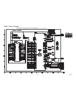
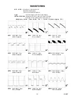


WAVEFORMS
L15DWF
9-1
1DIV: 50V 20
µ
s
WF1
GND
GND
GND
GND
GND
GND
1DIV: 50V 20
µ
s
1DIV: 5V 20
µ
s
1DIV: 5V 20
µ
s
1DIV: 10V 20
µ
s
WF2
WF3
WF4
GND
Input:
Color Bar Signal (with 1kHz Audio Signal)
INITIAL POSITION:
Unplug unit from AC outlet for at least 5 minutes.
reconnect to AC outlet and then turn power on.
(Brightness---Center Color---Center Tint --- Center Contrast---Approx 70%)
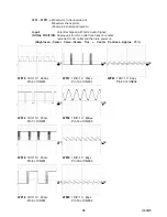
Pin 1 of CN571
Pin 4 of CN571
Pin 3 of WH501A
WF6
1DIV: 500mV 20
µ
s
Pin 31 of IC301
1DIV: 500mV 500
µ
s
1DIV: 2V 500
µ
s
Pin 3 of IC801
Pin 14 of IC801
WF10
WF11
WF12
1DIV: 10V 5ms
WF5
Pin 7 of IC551
1DIV: 1V 5ms
WF9
GND
GND
GND
GND
GND
Q571 Base
WF7
Q572 Collector
WF8
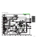
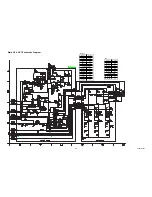
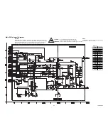
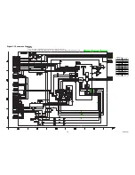
WF1 ~ WF21 =
Waveforms to be observed at
Waveform check points.
(Shown in Schematic Diagram.)
Q1512 Collector
Q1522 Collector
1DIV: 50V 20
µ
s
1DIV: 200V 20
µ
s
Q1532 Collector