


8-7
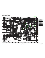
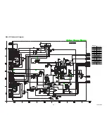
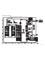
Main 5/5 Schematic Diagram
L3821SCM5
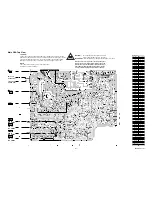
CAUTION !
Fixed voltage (or Auto voltage selectable) power supply circuit is used in this unit.
If Main Fuse (F601) is blown , check to see that all components in the power supply
circuit are not defective before you connect the AC plug to the AC power supply.
Otherwise it may cause some components in the power supply circuit to fail.
For continued protection against risk of fire,
replace only with same type 4 A, 125V fuse.
CAUTION ! :
ATTENTION :
Utiliser un fusible de rechange de m
ê
me type de 4A, 125V.
4A/125V
NOTE:
The voltage for parts in hot circuit is measured using
hot GND as a common terminal.
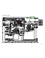
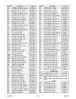
MAIN 5/5
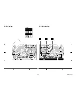
Ref No.
Position
IC601
BB-2
Q601
CC-2
Q602
CC-2
Q645
Z-2
Q646
Z-2
Q647
Y-2
Q652
AA-1
Q672
Z-3
Q673
Y-1
Q674
Z-1
Q681
AA-4
Q682
Z-4
Q696
AA-3
CN691
DD-4
VR661
Z-2
CONNECTOR
IC
VARIABLE RESISTOR
TRANSISTORS