


User Manual
Chapter 4
GFK-1742F
Jan 2020
Configuration
130
Tuning Parameter 6: Sets the encoder resolution. The parameter is only used in torque
mode. For correct torque mode operation, this value must be set to the number of
quadrature encoder counts (4X encoder lines) generated by the motor feedback device per
revolution. The user can determine the value from the feedback device specification. As a
double check, the user may wish to connect the feedback device to the DSM and manual
rotate the motor shaft one revolution. The reading on the DSM %AI data for actual position
should closely match (variations are caused by the accuracy of manual turning shaft one
revolution) the value placed in this parameter. The allowed range is 100-32767
counts/revolution. The default value is 4096 counts per revolution
Tuning Parameter 7: Sets the velocity regulator proportional gain. The parameter is only
used in torque mode. The proportional gain is multiplied by velocity error (velocity
command - velocity feedback) to generate the portion of the torque command due to the
proportional term. Correctly setting this value will determine how well the velocity
regulator performs in the control system. Appendix D describes a method to correctly tune
this parameter. The allowable range for the velocity loop proportional gain term is 0-32767.
The default value is 1500.
Tuning Parameter 8: Sets the velocity regulator integral gain. The parameter is only used in
torque mode. The integral gain is the term multiplied by the area of the velocity error
(velocity command - velocity feedback) to generate the portion of the torque command
due to the integral term. Correctly setting this value will determine how well the velocity
regulator performs in the control system. Appendix D describes a method to correctly tune
this parameter. The allowable range for the velocity loop proportional gain term is 0-32767.
The default value is 0.
Tuning Parameter 10: Sets the Torque Command Filter setting. The torque command filter
allows the user to activate a low pass filter for the velocity regulator output. . The filter is
typically used to keep the controller from exciting a machine resonance. The allowable
range for torque filter settings is 0
–
3. The default value is 0.
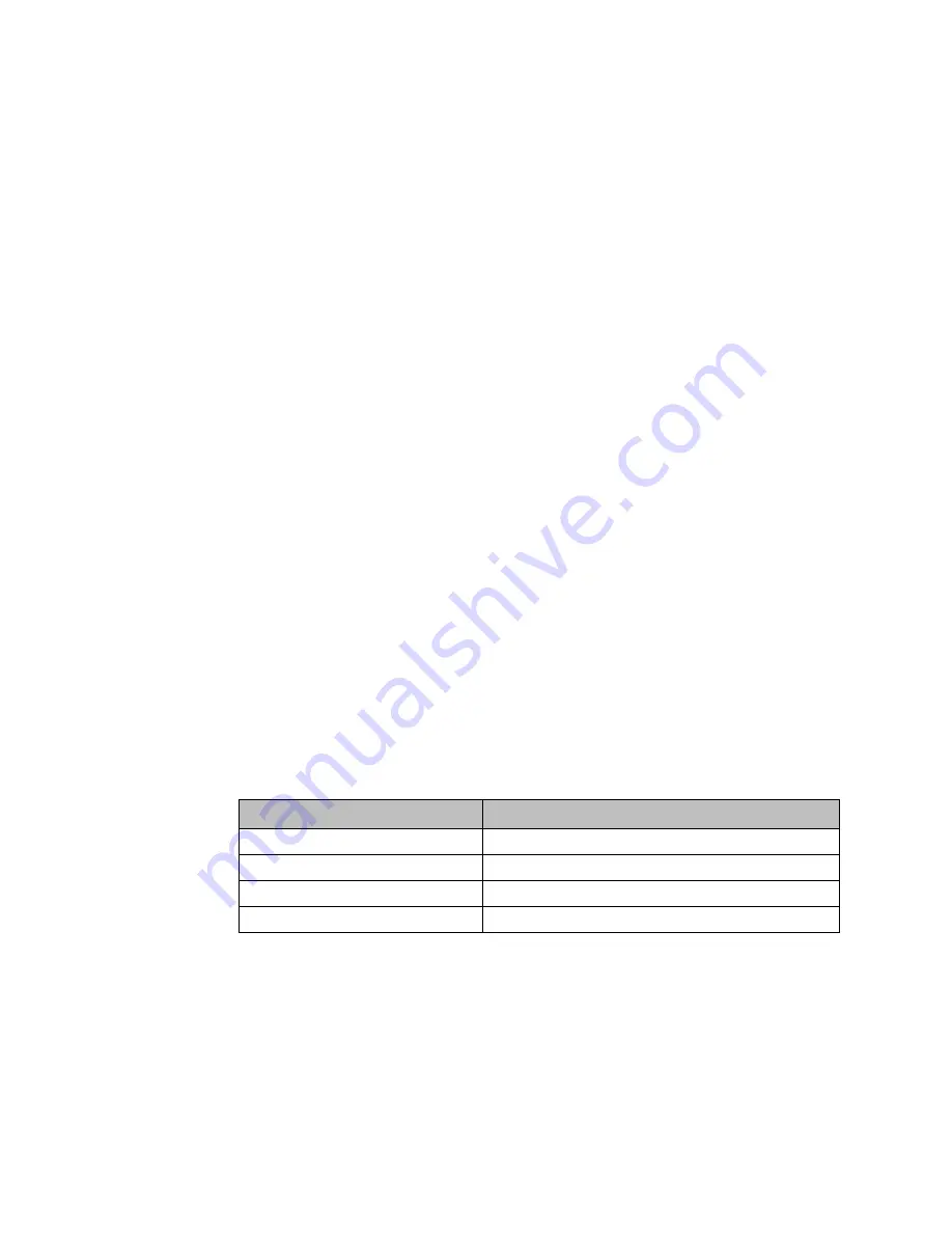
Table 39: Tuning Parameter 10 Values
Tuning Parameter 10 Values
Torque Command Low Pass Filter Setting
0
OFF1
1
Low Bandwidth Filter (150 Hz 3db point)
2
Medium Bandwidth Filter (250 Hz 3db point)
3
High Bandwidth Filter (350 Hz. 3db point)
4.3.10
Power Consumption Data
This is a display-only tab that indicates the power required by the DSM314 module.