AGL_HP_ST_ZHK1P_EN_Rev00
21
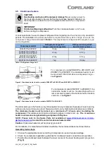
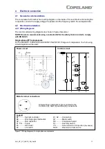
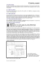
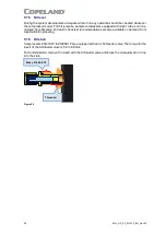
L1/T1 neutral connection
L2/T2 line voltage connection
S1, S2 thermistor chain connection
M1, M2 control circuit connection
4.2.3 Motor winding
The ZH scroll compressors are offered with either a single-phase or a three-phase induction motor,
depending on the size. All three-phase motors are connected in star; single-phase motors need a
run capacitor.
4.3 Motor insulation
The motor insulation material is class "B" (PF* and T
F
*) or "H" (T
W
*) f or compressor models
covered in these guidelines.
4.4 Motor protection
Independently from the internal motor protection, fuses must be installed before the c ompress or.
The selection of fuses has to be made according to VDE 0635, DIN 57635, IEC 269 -1 o r E N 60-
269-1 and compressor maximum operating current (MOC). Failing to install f uses bef ore the
compressor or selecting inappropriate fuses may result in compressor f ailure.
4.4.1 Internal line break motor protection
For the ZH04K1P to ZH19K1P and ZHI05K1P to ZHI40K1P range of compressors , c onventional
inherent internal line break motor protection is provided.
4.4.2 External protection with Kriwan
IMPORTANT
Different sources for power supply and contact M1-M2! Module
malfunction!
Use the same potential f or power supply and the switch
contact of the control loop (M1-M2).
The electronic motor protection system used in ZHI46K1P is identified by a "W" as the centre letter
in the motor code. This system utilizes the temperature-dependent resistance of t he t hermist ors
(also called PTC-resistance) to read the winding temperature. A chain of f our thermistors
connected in series is embedded in the motor windings so that the temperature of the thermist ors
can f ollow the winding temperature with little inertia. An electronic module is req uired to p rocess
the resistance values and trip a control depending on the thermistor resistance.
For protection in case of blocked rotor one thermistor for each phase is embedded in t he wind ing
heads on the upper (suction gas) side of the compressor motor. A fourth thermistor is located in a
winding head at the lower end of the motor. The entire chain is internally led t o t he f usite f rom
where it is connected to the module connections S1 and S2. When any resistance of the thermistor
chain reaches the tripping value, the module interrupts the control line and causes the compress or
to switch off. After the thermistor has cooled sufficiently, its resistance drops to the reset value but
the module itself resets after a time delay of 30 minutes and restarts the compressor.
Control circuit wiring
Figure 23: Wiring of the motor protection module

