background image


24 


C6.2.44/0219/E 

Maintenance & repair 

6.1  Exchanging the refrigerant 

Qualified refrigerants and oils are given in section 2.5.1. 

It is not necessary to replace the refrigerant with new unless contamination due to an error such 
as topping up the system with an incorrect refrigerant is suspected. To verify correct refrigerant 
composition, a sample can be taken for chemical analysis. A check can be made during shut down 
by  comparing  the  refrigerant  temperature  and  pressure  using  precision  measurements  at  a 
location in the system where liquid and vapour phases are present and when the temperatures 
have stabilised. 

In the event that the refrigerant needs replacing, the charge should be recovered using a suitable 
recovery unit. 

6.2  Rotalock valves 

Rotalock valves should be periodically retorqued to ensure that leak tightness is maintained. 

6.3  Replacing a compressor 


CAUTION 
Inadequate  lubrication!  Bearing  destruction!

  Exchange  the  accumulator 

after  replacing  a  compressor  with  a  burned  out  motor.  The  accumulator  oil 
return orifice or screen may be plugged with debris or may become plugged. 
This will result in starvation of oil to the new compressor and a second failure. 

6.3.1  Compressor replacement 

In  the  case  of  a  motor  burnout,  the  majority  of  contaminated  oil  will  be  removed  with  the 
compressor. The rest of the oil is cleaned through the use of suction and liquid line filter driers. A 
100%  activated  alumina  suction  line  filter  drier  is  recommended  but  must  be  removed  after 
72 hours. 

It is highly recommended that the suction accumulator be replaced if the system 

contains one.

 This is because the accumulator oil return orifice or screen may be plugged with 

debris or may become plugged shortly after a compressor failure. This will result in starvation of 
oil to the replacement compressor and a second failure. When a single compressor or tandem is 
exchanged in the field, it is possible that a major portion of the oil may still be in the system. While 
this may not affect the reliability of the replacement compressor, the extra oil will add to rotor drag 
and increase power usage. 

6.3.2  Start-up of a new or replacement compressor 

Rapid  charging  only  on  the  suction  side  of  a  scroll-equipped  system  or  condensing  unit  can 
occasionally result in a temporary no start condition for the compressor. The reason for this is that, 
if the flanks of the compressor happen to be in a sealed position, rapid pressurisation of the low 
side without opposing high-side pressure can cause the scrolls to seal axially. As a result, until the 
pressures eventually equalise, the scrolls can be held tightly together preventing rotation. The best 
way to avoid this situation is to charge on both the high and low sides simultaneously at a rate 
which does not result in axial loading of the scrolls. 

A minimum suction pressure of 1.75 bar must be maintained during charging. Allowing pressure 
to drop below 0.3 bar for more than a few seconds may overheat scrolls and cause early drive 
bearing damage. Never install a system in the field and leave it unattended when it has no charge, 
a  holding  charge,  or  with  the  service  valves  closed  without securely  electrically  locking  out  the 
system.  This  will  prevent  unauthorised  personnel  from  accidentally  operating  the  system  and 
potentially  ruining  the  compressor  by  operating  with  no  refrigerant  flow. 

Do  not  start  the 

compressor while the system is in a deep vacuum.

 Internal arcing may occur when a scroll 

compressor is started in a vacuum causing burnout of the internal lead connections. 


Summary of Contents for Copeland Scroll Digital ZRD36KRE

Page 1: ...Copeland ScrollDigital Compressors for comfort precision and process cooling ZRD36KRE to ZRD92KRE Application Guidelines Digital ...

Page 2: ...stallation location 7 3 1 4 Mounting parts 8 3 2 Solenoid valves for models ZRD KRE compressors 8 3 2 1 Solenoid valve installation General recommendations 9 3 2 2 Solenoid valve installation Tubing recommendations 9 3 3 Discharge check valve 10 3 4 Brazing procedure 10 3 5 Shut off valves and adaptors 11 3 6 Oil separator 12 3 7 Accumulators 12 3 8 Screens 12 3 9 Mufflers 12 3 10 Suction line noi...

Page 3: ...s 22 5 9 Starting sound 22 5 10 Deep vacuum operation 22 5 11 Shell temperature 22 5 12 Pump down cycle 22 5 13 Minimum run time 22 5 14 Sound characteristics 23 5 15 Shut off sound 23 5 16 Frequency 23 5 17 Oil level 23 5 18 Digital system control 23 5 19 Power factor 23 6 Maintenance repair 24 6 1 Exchanging the refrigerant 24 6 2 Rotalock valves 24 6 3 Replacing a compressor 24 6 3 1 Compressor...

Page 4: ...andards please refer to the Manufacturer s Declaration available at www climate emerson com en gb These instructions should be retained throughout the lifetime of the compressor You are strongly advised to follow these safety instructions 1 1 Icon explanation WARNING This icon indicates instructions to avoid personal injury and material damage CAUTION This icon indicates instructions to avoid prop...

Page 5: ... other materials in the area of the compressor do not get in touch with it Lock and mark accessible sections CAUTION Overheating Bearing damage Do not operate compressors without refrigerant charge or without being connected to the system CAUTION Contact with POE Material damage POE lubricant must be handled carefully and the proper protective equipment gloves eye protection etc must be used at al...

Page 6: ...D72KRE 5 14 6 03 TFD ZRD92KRE 6 26 7 51 TFD Table 1 Cooling capacity for ZRD KRE compressors 10 C 45 C 10K 0K Copeland Scroll Digital compressors have one scroll compression set driven by a single or three phase induction motor The Scroll set is mounted at the upper end of the rotor shaft of the motor The rotor shaft axis is in the vertical plane 2 2 Nomenclature The model designation contains the...

Page 7: ...36KRE 435 3 417 2 366 4 264 6 222 8 75 3 49 8 19 ZRD48KRE 466 448 397 1 294 1 252 5 75 3 49 8 22 2 ZRD61 72KRE 25 6 412 1 296 7 230 2 236 2 79 6 47 6 12 7 ZRD92KRE 129 7 412 1 296 7 230 2 236 2 79 6 47 6 19 Table 2 Dimensions Digital scroll ZRD KRE Figure 1 Dimensions of models ZRD36KRE ZRD48KRE ...

Page 8: ...C6 2 44 0219 E 5 Figure 2 Dimensions of models ZRD61KRE to ZRD92KRE ...

Page 9: ...R513A Copeland brand products standard oil Emkarate RL 32 3MAF Servicing oils Emkarate RL 32 3MAF Mobil EAL Arctic 22 CC Table 3 Qualified refrigerants and oils 2 5 2 Application limits and operating envelopes CAUTION Inadequate lubrication Compressor breakdown The superheat at the compressor suction inlet must always be sufficient to ensure that no refrigerant droplets enter the compressor For a ...

Page 10: ...aks If possible the compressor should be kept vertical during handling The discharge connection plug should be removed first before pulling the suction connection plug to allow the dry air pressure inside the compressor to escape Pulling the plugs in this sequence prevents oil mist from coating the suction tube making brazing difficult The copper coated steel suction tube should be cleaned before ...

Page 11: ... to the high life cycle requirements in a hot gas environment a special valve has been developed A screen is provided in the digital solenoid valve to prevent debris from disrupting valve operation For reliability requirements only Emerson approved solenoid valves may be used for this application All compressor warranties are null and void if the Emerson approved valve is not used For digital sole...

Page 12: ...ll filter mesh to avoid large particles entering the inside see Figure 7 which could lead to a defect and blockage The filter is part of the valve delivery and already crimped inside it cannot be changed This is different from previous valve body versions where the filter was delivered loose to the valve body and could be exchanged The recommended tightening torque for the screw to fix the coil on...

Page 13: ...ded to support the operation of the unloader mechanism To avoid by passing during the unloading process back to suction a dynamic discharge valve is fitted internally on the discharge port of the fixed scroll This discharge valve cannot be used with recycling pump down because it is not leak proof during the off period 3 4 Brazing procedure IMPORTANT Blockage Compressor breakdown Maintain a flow o...

Page 14: ...ture is attained moving the torch up and down and rotating around the tube as necessary to heat the tube evenly Add braze material to the joint while moving the torch around the joint to flow braze material around the circumference After the braze material flows around the joint move the torch to heat area 3 This will draw the braze material down into the joint The time spent heating area 3 should...

Page 15: ... refrigerant can wash the oil off the bearings leading to overheating and bearing failure Irrespective of system charge oil dilution may occur if large amounts of liquid refrigerant repeatedly flood back to the compressor during normal off cycles defrost varying loads In such a case an accumulator must be used to reduce flood back to a safe level that the compressor can handle The use of accumulat...

Page 16: ...ting frequencies This is easily done by using one of the common combinations of recommended design configurations The scroll compressor makes both a rocking and twisting motion and enough flexibility must be provided in the line to prevent vibration transmission into any lines attached to the unit In a split system the most important goal is to ensure minimal vibration in all directions at the ser...

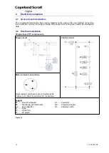
Page 17: ...ases and the frequency match the nameplate data 4 2 Electrical installation Single phase PF compressors Power circuit Control circuit Motor terminal connections Single phase compressors are connected to the Common C Start S and Run R connections Legend B1 Room thermostat K1 Contactor B3 Discharge gas thermostat R2 Crankcase heater C2 Run capacitor S1 Auxiliary switch F1 Fuse F3 HP switch F4 LP swi...

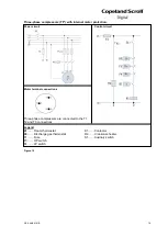
Page 18: ...Power circuit Control circuit Motor terminal connections Three phase compressors are connected to the T1 T2 and T3 connections Legend B1 Room thermostat K1 Contactor B3 Discharge gas thermostat R2 Crankcase heater F1 Fuse S1 Auxiliary switch F3 HP switch F4 LP switch Figure 15 ...

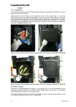
Page 19: ... relevant standard of application in their country region Examples of correct electrical installations are shown in Figures 16 17 below Figure 16 Correct electrical installation with cable glands for IP21 T box compressors ZRD36KRE ZRD48KRE Figure 17 Correct electrical installation with cable glands for IP21 T box compressors ZRD61KRE to ZRD92KRE 4 2 2 Motor winding Compressor model ZRD36KRE is av...

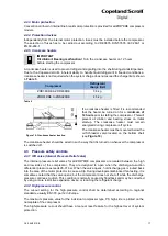
Page 20: ...r off cycles The crankcase heater must be mounted below the oil Schraeder valve located on the bottom shell see Figure 18 The crankcase heater should be wired in such a way that it is turned on whenever the compressor is switched off 4 3 Pressure safety controls 4 3 1 IPR valve Internal Pressure Relief valve The internal pressure relief valves for all ZRD KRE compressors are located between the hi...

Page 21: ... with a discharge temperature thermostat The discharge thermostat dedicated to R450A and R513A has a cut out setting of 130 C 4K with closing at 101 C 8K and should be installed approximately 120 mm from the discharge valve outlet see assembly instructions below To ensure proper functioning and to avoid false readings the discharge line thermostat must be installed and insulated according to the p...

Page 22: ...ter final assembly Each motor phase winding is tested according to EN 0530 or VDE 0530 part 1 at a differential voltage of 1000V plus twice the nominal voltage Since high voltage tests lead to premature ageing of the winding insulation further additional tests of that nature are not recommended If it has to be done for any reason a lower voltage must be used Disconnect all electronic devices eg mo...

Page 23: ...s at the furthest point from the compressor in the suction and liquid lines is advisable Pressure must be measured using a vacuum pressure gauge on the access valves and not on the vacuum pump this serves to avoid incorrect measurements resulting from the pressure gradient along the connecting lines to the pump Evacuating the system only on the suction side of a Scroll compressor can occasionally ...

Page 24: ...re important to ensure that new compressors are not subjected to liquid abuse and high pressure run tests It is not good practice to use the compressor to test the high pressure switch function on the production line Switch function can be tested with nitrogen prior to installation and wiring can be checked by disconnecting the high pressure switch during the run test 5 7 Rotation direction Copela...

Page 25: ...sor drive bearing ZRD scrolls incorporate internal low vacuum protection the floating seal unloads when the pressure ratio exceeds approximately 10 1 5 11 Shell temperature The top shell and discharge line can briefly but repeatedly reach temperatures above 177 C if the compressor cycles on its internal protection devices This only happens under rare circumstances and can be caused by the failure ...

Page 26: ...Copeland scroll compressors for use with variable speed AC drives There are numerous issues that must be considered when applying Scroll compressors with variable speed including system design inverter selection and operating envelopes at various conditions Only frequencies from 50 Hz to 60 Hz are acceptable Operation outside this frequency range is possible but should not be done without specific...

Page 27: ...ged with debris or may become plugged shortly after a compressor failure This will result in starvation of oil to the replacement compressor and a second failure When a single compressor or tandem is exchanged in the field it is possible that a major portion of the oil may still be in the system While this may not affect the reliability of the replacement compressor the extra oil will add to rotor...

Page 28: ...rption of moisture in ester oil in comparison to mineral oil in ppm by weight at 25 C and 50 relative humidity h hours If the moisture content of the oil in a refrigeration system reaches unacceptably high levels corrosion and copper plating may occur The system should be evacuated down to 0 3 mbar or lower If there is uncertainty as to the moisture content in the system an oil sample should be ta...

Page 29: ...product literature and assembly line repair areas If compressor removal is required the compressor should be cut out of system rather than unbrazed 7 Dismantling disposal Removing oil and refrigerant Do not disperse in the environment Use the correct equipment and method of removal Dispose of oil and refrigerant according to national legislation and regulations Dispose of compressor according to n...

Page 30: ...00 Fax 971 4 886 54 65 mea sales emerson com ASIA PACIFIC Suite 2503 8 25 F Exchange Tower 33 Wang Chiu Road Kowloon Bay Kowloon Hong Kong Tel 852 2866 3108 Fax 852 2520 6227 CZECH REPUBLIC Hajkova 22 CZ 133 00 Prague Tel 420 733 161 651 Fax 420 271 035 655 Pavel Sudek emerson com SPAIN PORTUGAL C Pujades 51 55 Box 53 ES 08005 Barcelona Tel 34 93 412 37 52 iberica sales emerson com RUSSIA CIS Dubi...

Reviews: