background image

Installation, Operation and Maintenance Manual

MAN-02-05-62-0742-EN  Rev. 0

December 2019

Safety

Section 2: Safety

2.1 

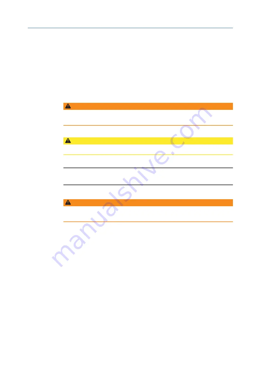
Warning Levels used in Manuals

The following warning levels are used in the documentation of Bettis for the safety of 
people and equipment.

 WARNING

Indicates a potentially hazardous situation which, if not avoided, could result in death or 
serious injury.

 CAUTION

Indicates a potentially hazardous situation which, if not avoided, may result in property damage.

NOTE:

Indicates important information regarding the product.

 WARNING

All personnel that handles Bettis actuators shall take part of and understand the 
following information prior to handling the system. See warnings on following page.

4

Section 2: Safety

Summary of Contents for Bettis BHH 1000

Page 1: ...Installation Operation and Maintenance Manual MAN 02 05 62 0742 EN Rev 0 December 2019 Bettis BHH Series HydraulicDouble ActingBalancedRotaryActuator90 Quarter Turn ...

Page 2: ......

Page 3: ...ervice Area 7 3 5 Mounting Directions of Actuators on Butterfly Valves 8 3 6 Flange and Stem on Butterfly Valves 9 3 7 Examples of different Installations of BHH on Valves 9 3 8 Choice of Hydraulic Oil 11 3 8 1 Viscosity Temperature Coefficient 11 3 8 2 Selection Diagram 12 Section 4 BHH Mounting 4 1 BHH Mounted on Valve ISO 5211 13 4 1 1 Preparations before Mounting 13 4 2 BHH Mounting on Butterf...

Page 4: ...tion of BHH Actuators 25 8 3 1 Opening by Emergency Operation Key BHH 125 to BHH 500 25 8 3 2 Operating by Portable Hand Pump BHH 125 to BHH 32000 26 8 3 3 Operating by Directed Mounted Hand Pump 27 8 3 4 Operating by Portable Hand Pump Submerged Actuator 27 Section 9 Service and Maintenance Section 10 BHH Dismounting 10 1 BHH Mounted on Butterfly Valve 29 10 1 1 Preparations before Dismounting 29...

Page 5: ...arts Spare and Material List for BHH 500 48 Section 17 Spare Parts BHH 1000 17 1 Parts Spare and Material List for BHH 1000 51 Section 18 Spare Parts BHH 2000 18 1 Parts Spare and Material List for BHH 2000 54 Section 19 Spare Parts BHH 4000 19 1 Parts Spare and Material List for BHH 4000 57 Section 20 Spare Parts BHH 8000 20 1 Parts Spare and Material List for BHH 8000 60 Section 21 Spare Parts B...

Page 6: ...vice life and functional reliability of hydraulic systems and their components are dependent on correct handling installation maintenance and repair to ensure fault free operation Instructions directly attached to the equipments e g nominal pressure must be observed The system must not be operated over the permissible operating range For detailed information please refer to the final specification...

Page 7: ...Installation Operation and Maintenance Manual MAN 02 05 62 0742 EN Rev 0 December 2019 Overview 1 2 Torque Performance BHH 125 BHH 250 BHH 500 BHH 1000 BHH 2000 BHH 4000 2 Section 1 Overview ...

Page 8: ...December 2019 Installation Operation and Maintenance Manual MAN 02 05 62 0742 EN Rev 0 Overview BHH 8000 BHH 32000 BHH 16000 3 Section 1 Overview ...

Page 9: ... WARNING Indicates a potentially hazardous situation which if not avoided could result in death or serious injury CAUTION Indicatesapotentiallyhazardoussituationwhich ifnotavoided mayresultinpropertydamage NOTE Indicates important information regarding the product WARNING All personnel that handles Bettis actuators shall take part of and understand the following information prior to handling the s...

Page 10: ...of the product WARNING High voltage that may be present on leads could cause electrical shock Avoid contact with live leads and terminals Before working on any electrical units the wiring has to be disconnected and circuits de energized Disconnect power to any electrical unit you are to replace WARNING Avoid shearing forces and tension on pipelines and components Piping must be strong enough to ca...

Page 11: ... dust Moist conditions should be avoided The equipments should be stored in an easily accessible place where they can be easily brought out for rigging work 3 1 2 Transport and Storage Use proper lifting facilities and transportation equipment In case of lifting take care not to damage the painting Scratches or damage of a coated area can cause galvanic corrosion If scratched repair before equipme...

Page 12: ...used System components were not bled of air Hydraulic actuator was not bled seal damage Limit switches were adjusted too close Hysteresis of the pressure switch was not taken into account during setting up Hydraulic pump was not filled with pressure fluid before commissioning 3 3 Placing the BHH When deciding where to place the BHH there are several aspects to consider before actually mounting the...

Page 13: ...ts it must be stated at the valve list This instruction applies for Bettis BHH actuators Figure 2 Examples of actuators positions on valves B Behind F Front L Left and R Right NOTE Position L and R might require a 90 Turn set indication plate to show correct position of the indication groove See Mounting 90 Turn Set Indication Plate on Section 6 Picture 1 Placement B Flow direction Flow direction ...

Page 14: ...f BHH on Valves Figure 3 Valve with Standard ISO5211 This example shows a BHH mounted on a Wouter Witzel EVFS with ISO 5211 Table 1 BHH Flange Stem Size Flange ISO 5212 DIN 6885 DIN79 Intrusion 125 F05 F07 ø17 ø16 45 250 N A F07 ø25 ø24 50 500 F07 F10 ø35 ø30 55 1000 F10 F12 ø42 ø36 63 2000 F12 F14 ø58 ø50 75 4000 F14 F16 ø74 ø63 85 8000 F16 F25 ø95 ø80 105 16000 F25 F30 ø95 ø85 132 32000 F30 F35 ...

Page 15: ...h moisture Figure 5 Ball Valves Smaller ball valve sizes can be of ISO5211 pattern but with threaded holes which requires mounting from top this means either a special flange or an additional box section bracket If the valve is with the box section bracket the adaption is similar to the one for High Performance valves however the adapter may need to extrude Larger sizes ball valves can have Standa...

Page 16: ...ly and scientifically other conditions than the viscosity e g the vapor pressure which determine the lubricating characteristics of the oil and minimize the risk of pump cavitation but based on experience a viscosity within the range 15 cSt min and 200 cSt can comply with the above mentioned conditions The choice of oil is not only a choice of viscosity but also an evaluation of how cold and warm ...

Page 17: ...ity with ambient temperature consider pour point where necessary and optimum operating viscosity according to system and operating data In case of operation for a long time at temperatures exceeding 70 C the oil will be broken down and thus loose its lubricating properties In order to guarantee a long service life for the installation a good and reliable filtration is necessary 12 Section 3 Instal...

Page 18: ... at service NOTE For placement and ID no see assembly drawing CAUTION At assembly of actuator on valve be aware to leave space enough for the adaptor between actuator and valve This means that the actuator by itself can fall down on the intermediate flange before tightening 4 2 BHH Mounting on Butterfly Valve Mounting BHH on Valve 1 Mount the bearing to fit the flange insert 2 Mount the pin 3 Moun...

Page 19: ...n the screws 12 Mount the seal 13 Mount the actuator 14 Mount the banana washers and screws Do not tighten 15 Adjust the butterfly valve disc See Adjusting the Valve Disc on Section 5 16 Tighten the screw 17 Test the valve for tightness NOTE If using butterfly valves with vulcanized rubber please follow the instruction for Adjusting the Valve Disc on Section 5 14 Section 4 BHH Mounting ...

Page 20: ...9 Tighten all screws and operate the actuator about 10 times into closed and afterwards into open position to check that the stem does not seize Throttle speed 10 Check that the bore of the ball is in line with the bore of the housing 11 If not so the adjusting screws are adjusted until the bores are in line 12 The adjustment shall always be completed with operation as under item 5 and afterwards ...

Page 21: ... the valve so that the indicator groove follows the disc The nut counter nut is loosely tightened 2 Check that there is no gap between actuator and adaption flange It has to be assured that there is proper contact in sealing area and around bolt areas 3 The rubber seat on the valve is soaped with water containing toilet soap 4 The hydraulic pressure is increased to the actuator test pressure and t...

Page 22: ...tors with LPU or LPUM might not correlate to the time stated in the table then use the Table 4 on Section 5 1 3 and Table 5 on Section 5 1 4 Table 2 Valve diameter mm Open closing time s 50 3 6 100 7 10 150 11 14 200 15 18 250 19 22 300 23 26 350 27 30 400 31 35 450 35 40 500 36 42 550 43 50 600 47 55 650 51 60 700 55 65 750 60 70 800 63 75 17 Section 5 Adjusting the Valve Disc ...

Page 23: ...sc see valve list if the working pressure is not known the setting for 0 6 bar is used mm over 0 6 bar over 6 10 bar over 10 16 bar WORLD VALVE 0 16 bar 50 3 2 1 2 65 3 2 1 2 80 4 3 1 2 100 5 3 2 2 125 7 4 2 4 150 8 5 3 4 175 9 6 3 4 200 10 7 3 4 250 13 9 4 5 300 16 10 5 5 350 18 12 6 5 400 21 14 7 5 450 24 16 8 8 500 26 17 9 8 600 31 21 10 8 700 37 24 12 10 800 42 28 14 10 1000 52 35 17 10 α 3 ta...

Page 24: ...d for LPUM D Standard closing time in second for LPUM S with ø0 4 mm blend Closing time in second for LPUM S with ø0 3 mm blend only used in special cases BHH F125 7 11 2 4 8 BHH F250 11 20 4 7 15 BHH F500 24 36 8 12 30 5 1 4 Opening and Closing Time for LPU on Actuator See Table 5 below for possible opening and closing times for LPU on actuator Table 5 Actuator type Open closing times for LPU D B...

Page 25: ...cator Turn Set is to turn the position groove in the position shaft 90 It is used when the BHH BHHF actuator is oriented so that the original indicator groove would indicate opposite of the correct Figure 9 BHH without indicator part left and BHH with indicator part turned 90 right Indication Plate M3 Screw 20 Mounting 90 Turn Set Section 6 Mounting 90 Turn Set ...

Page 26: ... the drill as shown on the picture The drill socket must be as closely as possible to the jig when it is tightened 3 The jig is mounted on the actuator 4 Drill until the socket reaches the jig Depth of the hole 7 5 mm 5 The thread expander is mounted in the hole in the shaft 6 Place the enclosed pin in the hole of the expander Knock the pin slightly to fix the thread expander 7 Thread expander mou...

Page 27: ...nents will be damaged if system flushing is done through these components and other components will make flushing impossible because flushing cannot be done through them 7 1 Flushing Procedure Piping system must be flushed before it is connected to Bettis components In the event that this is not possible all Bettis components must be by passed during flushing Each individual customer yard is free ...

Page 28: ...out a pressure test on the pipes System pressure 1 5 if not otherwise stated During pressure test possible leakages can be detected Hereafter flushing can be carried out taking the following factors into consideration flow in l min viscosity in cSt pipe length inside pipe diameter The stated factors can be read from the attached list Oil samples can periodically be taken of the return pipe at the ...

Page 29: ...xample ABS Max operating pressure 20 of burst pressure For extreme cycle speeds loads and lifetime expectations please consult manufacturer 8 2 Turning Direction in Relation to A and B Figure 10 Pressure on A Indicator slot is moving clockwise Valve closed and indicator slot is parrallel to mounting area Pressure on B Indicator slot is moving counter clockwise Valve open and indicator slot is perp...

Page 30: ...ockwise to close valve 4 After emergency operation by key the crossover valve is closed 8 3 Emergency Operation of BHH Actuators Oil pressure loss necessitates emergency operation of the actuator The emergency operation can be carried out by hand pump for all BHH models and alternatively by key adjustable spanner for BHH 125 to BHH 500 NOTE Emergency operation by means of hand pump unit is solely ...

Page 31: ... Select on the hand pump whether to operate towards open or closed 3 Pump with the hand pump until the required position is reached Figure 11 Pressure on A Indicator slot is moving clockwise Valve closed and indicator slot is parrallel to mounting area Pressure on B Indicator slot is moving counter clockwise Valve open and indicator slot is perpendicular to the mounting area A A B B 26 Operating S...

Page 32: ...l Figure 12 8 3 4 Operating by Portable Hand Pump Submerged Actuator 1 Close the stop valves 2 Connect the hoses via quick connections A to port A and B to port B 3 Select on the hand pump whether to operate towards open or closed 4 Pump with the hand pump until the required position is reached 5 After operation open the stop valves Figure 13 Instruction plate Hand pump handle Direction valve Stop...

Page 33: ...intenance Manual MAN 02 05 62 0742 EN Rev 0 December 2019 Section 9 Service and Maintenance The BHH actuator requires little to no maintenance during its life cycle time 28 Service and Maintenance Section 9 Service and Maintenance ...

Page 34: ...into open and closed positions On small BHH sizes a key is used and on large actuators compressed air is used for turning the actuator Before disassembly the actuator is turned into closed position i e the groove on the shaft has to be parallel to the port surface as shown in the pictures below Figure 14 Shall be parallel for closed pos BHH 125 BHH 500 are operated by key BHH 1000 BHH 32000 are op...

Page 35: ...knocking the position shaft with a nylon hammer The spline shaft and the housing are to be marked 6 The spline shaft is dismounted 7 For BHH 1000 to 32000 there might be a spline connection to be removed as well Otherwise remove screws or Seeger ring locking ring 8 The top part is dismounted Use special tools or 2 pins fitting the holes in the top part Turn clockwise to loosen the top part 9 Remov...

Page 36: ...ton 13 The piston is dismounted 14 Dismount the cross over valve 15 The spindle shall be tightened for the valve seat to be drawn out at dismounting Note If the valve seat does not come out the first time the housing is mounted again and the spindle is tightened whereupon the housing is unscrewed together with the valve seat Valve Seat Spindle 31 BHH Dismounting Section 10 BHH Dismounting ...

Page 37: ... O rings and X rings are laid in hydraulic oil before mounting Mounting of seals must be carried out in clean environment no burrs nicks and chips All O rings X rings are replaced at service Mounting of Seals 1 Mount O ring on position shaft Mounting of Seals on Piston 1 The outer X rings are mounted on the piston 2 Mount the lower inner X ring 3 Mount the upper inner X ring 32 BHH Re Mounting Sec...

Page 38: ...tom Cover and Housing 1 Mount the X ring in bottom part 2 Mount the X ring in housing Mounting of Cross over Valve in Actuator Housing 1 The valve seat is lubricated with an sufficient amount of oil on the O ring before mounting 2 Mount the valve seat with a mounting tool sized to fit the smallest hole not to damage the seat 3 The seat is pushed to stop 4 The Stop valve is mounted in the housing b...

Page 39: ...turning counter clockwise tightening torque stated on the assembly drawing Mounting of Spline Shaft and Positioning Shaft 1 The serrated lock washer is mounted in the positioning shaft can possibly be fixated with a drop of Loctite Note Always use a new lock washer 2 The positioning shaft is mounted in the spline shaft according to the disassembly marks New parts have to be positioned according to...

Page 40: ...n splined shaft ready for Seeger ring mounting 9 The positioning shaft is mounted in the splined shaft and then the seeger ring is mounted Assembled spline and positioning shaft are positioned in the housing with the piston pressed home 10 The housing is marked see dimensions on assembly drawing If the housing is marked at disassembly the marks are used for assembly 11 Spline shaft is mounted The ...

Page 41: ...reased side downwards and the other side is greased with the remaining grease 3 The last thrust bearing is mounted Mounting of Bottom Part and Cover 1 Mount the bottom cover part turn clockwise 2 The bottom cover is tightened with special tools Tightening torque is stated on drawing If special tools are not available pins fitting into the holes are to be used 3 When the bottom cover has been tight...

Page 42: ... 0 Mounting of Yoke 1 Yoke must easily fit into the hole 2 Mount the Yoke Final Test 1 The assembled actuator shall be able to operate with air approx 3 bar Check that it is operating 90 2 Finally the actuator shall be tested hydraulically 37 BHH Re Mounting Section 11 BHH Re Mounting ...

Page 43: ...mm Allen key Figure 15 12 1 Operating Time for Valve Open Closed Following table shows the traveling time of opening and closing of hydraulic remote controlled valve which has to be kept for protecting the valve from bad effect caused by quick opening and closing the valve Quick closing valve and the valve which is necessary to be quick acting by special circumstance and rule requirement shall be ...

Page 44: ...0 750 30 30 90 300 12 12 36 800 32 32 96 350 14 14 42 850 34 34 102 400 16 16 48 900 36 36 108 450 18 18 54 1000 40 40 120 500 20 20 60 1000 40 120 1 The operating time recommended in this table is made based on 1 to 3 seconds per inch not minimum or maximum time this mean variable tolerances under normal ambient temperature NOTE When the operating time is set at the actual ambient temperature it ...

Page 45: ...k pressure at actuator by mean of quick connectors Actuator valve does not keep the last order position Pilot operated check valve on the actuator Actuator valve traveling time is too fast or too slow Pilot operated check valve on the actuator Note When the operating time is set at the actual ambient temperature it may fluctuate with the operating viscosity which is changeable according to operati...

Page 46: ... ring 31 Banna Washer 1 Housing 23 Set Screws 4 Position Shaft 13 O ring 11 X ring 5 Splined Shaft 19 Thrust Washer 6 Bottom Cover 10 X ring 18 Thrust Cage 17 M8 Screw 8 Washer 26 Plug 27 Yoke 23 Set Screws 22 Stop Valve 25 Valve Seat 34 Screws 11 X ring 15 O ring 3 Top Part 7 Top Part Cover 30 Angle Bearing 41 Spare Parts BHH 125 Section 14 Spare Parts BHH 125 ...

Page 47: ...02 05 62 0742 EN Rev 0 December 2019 14 1 Parts Spare and Material List for BHH 125 Emerson Automation Solutions Actuation Technologies 19200 Northwest Freeway Houston TX 77065 USA T 1 281 477 4100 42 Spare Parts BHH 125 Section 14 Spare Parts BHH 125 ...

Page 48: ... Operation and Maintenance Manual MAN 02 05 62 0742 EN Rev 0 Emerson Automation Solutions Actuation Technologies 19200 Northwest Freeway Houston TX 77065 USA T 1 281 477 4100 43 Spare Parts BHH 125 Section 14 Spare Parts BHH 125 ...

Page 49: ... ring 31 Banna Washer 1 Housing 23 Set Screws 4 Position Shaft 13 O ring 11 X ring 5 Splined Shaft 19 Thrust Washer 6 Bottom Cover 10 X ring 18 Thrust Cage 17 M8 Screw 8 Washer 26 Plug 27 Yoke 23 Set Screws 22 Stop Valve 25 Valve Seat 34 Screws 11 X ring 15 O ring 3 Top Part 7 Top Part Cover 30 Angle Bearing 44 Spare Parts BHH 250 Section 15 Spare Parts BHH 250 ...

Page 50: ...ce Manual MAN 02 05 62 0742 EN Rev 0 15 1 Parts Spare and Material List for BHH 250 Emerson Automation Solutions Actuation Technologies 19200 Northwest Freeway Houston TX 77065 USA T 1 281 477 4100 45 Spare Parts BHH 250 Section 15 Spare Parts BHH 250 ...

Page 51: ... Maintenance Manual MAN 02 05 62 0742 EN Rev 0 December 2019 Emerson Automation Solutions Actuation Technologies 19200 Northwest Freeway Houston TX 77065 USA T 1 281 477 4100 46 Spare Parts BHH 250 Section 15 Spare Parts BHH 250 ...

Page 52: ... ring 31 Banna Washer 1 Housing 23 Set Screws 4 Position Shaft 13 O ring 11 X ring 5 Splined Shaft 19 Thrust Washer 6 Bottom Cover 10 X ring 18 Thrust Cage 17 M8 Screw 8 Washer 26 Plug 27 Yoke 23 Set Screws 22 Stop Valve 25 Valve Seat 34 Screws 11 X ring 15 O ring 3 Top Part 7 Top Part Cover 30 Angle Bearing 47 Spare Parts BHH 500 Section 16 Spare Parts BHH 500 ...

Page 53: ...02 05 62 0742 EN Rev 0 December 2019 16 1 Parts Spare and Material List for BHH 500 Emerson Automation Solutions Actuation Technologies 19200 Northwest Freeway Houston TX 77065 USA T 1 281 477 4100 48 Spare Parts BHH 500 Section 16 Spare Parts BHH 500 ...

Page 54: ... Operation and Maintenance Manual MAN 02 05 62 0742 EN Rev 0 Emerson Automation Solutions Actuation Technologies 19200 Northwest Freeway Houston TX 77065 USA T 1 281 477 4100 49 Spare Parts BHH 500 Section 16 Spare Parts BHH 500 ...

Page 55: ...Spare Parts BHH 1000 17 M4 Screw 7 Top part cover 3 Top part 12 X ring 14 O ring 16 O ring 9 X ring 27 Valve Seat 24 Stop Valve 29 Yoke 13 O ring 19 Thrust cage 2 Piston 1 Housing 4 Position Shaft 5 Splined Shaft 20 Thrust washer 6 Bottom cover 50 Spare Parts BHH 1000 Section 17 Spare Parts BHH 1000 ...

Page 56: ...e Manual MAN 02 05 62 0742 EN Rev 0 17 1 Parts Spare and Material List for BHH 1000 Emerson Automation Solutions Actuation Technologies 19200 Northwest Freeway Houston TX 77065 USA T 1 281 477 4100 51 Spare Parts BHH 1000 Section 17 Spare Parts BHH 1000 ...

Page 57: ...Maintenance Manual MAN 02 05 62 0742 EN Rev 0 December 2019 Emerson Automation Solutions Actuation Technologies 19200 Northwest Freeway Houston TX 77065 USA T 1 281 477 4100 52 Spare Parts BHH 1000 Section 17 Spare Parts BHH 1000 ...

Page 58: ...arts BHH 2000 17 M4 Screw 7 Top part cover 3 Top part 12 X ring 14 O ring 16 O ring 9 X ring 27 Valve Seat 24 Stop Valve 29 Yoke 13 O ring 19 Thrust cage 2 Piston 1 Housing 4 Position Shaft 5 Splined Shaft 20 Thrust washer 6 Bottom cover 23 M10 Screw 53 Spare Parts BHH 2000 Section 18 Spare Parts BHH 2000 ...

Page 59: ...2 05 62 0742 EN Rev 0 December 2019 18 1 Parts Spare and Material List for BHH 2000 Emerson Automation Solutions Actuation Technologies 19200 Northwest Freeway Houston TX 77065 USA T 1 281 477 4100 54 Spare Parts BHH 2000 Section 18 Spare Parts BHH 2000 ...

Page 60: ...Operation and Maintenance Manual MAN 02 05 62 0742 EN Rev 0 Emerson Automation Solutions Actuation Technologies 19200 Northwest Freeway Houston TX 77065 USA T 1 281 477 4100 55 Spare Parts BHH 2000 Section 18 Spare Parts BHH 2000 ...

Page 61: ...arts BHH 4000 17 M4 Screw 7 Top part cover 3 Top part 12 X ring 14 O ring 16 O ring 9 X ring 27 Valve Seat 24 Stop Valve 29 Yoke 13 O ring 19 Thrust cage 2 Piston 1 Housing 4 Position Shaft 5 Splined Shaft 20 Thrust washer 6 Bottom cover 23 M10 Screw 56 Spare Parts BHH 4000 Section 19 Spare Parts BHH 4000 ...

Page 62: ...e Manual MAN 02 05 62 0742 EN Rev 0 19 1 Parts Spare and Material List for BHH 4000 Emerson Automation Solutions Actuation Technologies 19200 Northwest Freeway Houston TX 77065 USA T 1 281 477 4100 57 Spare Parts BHH 4000 Section 19 Spare Parts BHH 4000 ...

Page 63: ...Maintenance Manual MAN 02 05 62 0742 EN Rev 0 December 2019 Emerson Automation Solutions Actuation Technologies 19200 Northwest Freeway Houston TX 77065 USA T 1 281 477 4100 58 Spare Parts BHH 4000 Section 19 Spare Parts BHH 4000 ...

Page 64: ...1 M16 Screw 50 M12 Screw 2 Piston 15 O ring 1 Housing 4 Position Shaft 13 O ring 10 X ring 5 Splined Shaft 20 Thrust Washer 6 Bottom Cover 11 X ring 19 Thrust Cage 28 Plug 29 Yoke 24 Stop Valve 27 Valve Seat 18 Snap ring 9 X ring 12 X ring 14 O ring 3 Top Part 7 Top Part Cover 59 Spare Parts BHH 8000 Section 20 Spare Parts BHH 8000 ...

Page 65: ...2 05 62 0742 EN Rev 0 December 2019 20 1 Parts Spare and Material List for BHH 8000 Emerson Automation Solutions Actuation Technologies 19200 Northwest Freeway Houston TX 77065 USA T 1 281 477 4100 60 Spare Parts BHH 8000 Section 20 Spare Parts BHH 8000 ...

Page 66: ...Operation and Maintenance Manual MAN 02 05 62 0742 EN Rev 0 Emerson Automation Solutions Actuation Technologies 19200 Northwest Freeway Houston TX 77065 USA T 1 281 477 4100 61 Spare Parts BHH 8000 Section 20 Spare Parts BHH 8000 ...

Page 67: ...Maintenance Manual MAN 02 05 62 0742 EN Rev 0 December 2019 Emerson Automation Solutions Actuation Technologies 19200 Northwest Freeway Houston TX 77065 USA T 1 281 477 4100 62 Spare Parts BHH 8000 Section 20 Spare Parts BHH 8000 ...

Page 68: ...1 M16 Screw 50 M12 Screw 2 Piston 15 O ring 1 Housing 4 Position Shaft 13 O ring 10 X ring 5 Splined Shaft 20 Thrust Washer 6 Bottom Cover 11 X ring 19 Thrust Cage 28 Plug 29 Yoke 24 Stop Valve 27 Valve Seat 18 Snap ring 9 X ring 12 X ring 14 O ring 3 Top Part 7 Top Part Cover 63 Spare Parts BHH 16000 Section 21 Spare Parts BHH 16000 ...

Page 69: ...05 62 0742 EN Rev 0 December 2019 21 1 Parts Spare and Material List for BHH 16000 Emerson Automation Solutions Actuation Technologies 19200 Northwest Freeway Houston TX 77065 USA T 1 281 477 4100 64 Section 21 Spare Parts BHH 16000 Spare Parts BHH 16000 ...

Page 70: ...peration and Maintenance Manual MAN 02 05 62 0742 EN Rev 0 Emerson Automation Solutions Actuation Technologies 19200 Northwest Freeway Houston TX 77065 USA T 1 281 477 4100 65 Spare Parts BHH 16000 Section 21 Spare Parts BHH 16000 ...

Page 71: ...aintenance Manual MAN 02 05 62 0742 EN Rev 0 December 2019 Emerson Automation Solutions Actuation Technologies 19200 Northwest Freeway Houston TX 77065 USA T 1 281 477 4100 66 Section 21 Spare Parts BHH 16000 Spare Parts BHH 16000 ...

Page 72: ...g and Backup ring 29 Oring 1 Housing 27 O ring 9 Position Shaft 25 O ring 28 O ring 20 O ring 5 6 Thrust Cage 21 X ring 24 Snap Ring 26 Backup Ring 27 Shaft Seal 15 Plug 14 Yoke 16 Stop Valve 2 Cylinder 32 O ring 33 Guiding Element 10 Top Cover 12 Top Part 17 Valve Seat 28 Piston Seal 3 Splined Shaft 4 Thrust Washer 7 Bottom Cover 67 Spare Parts BHH 32000 Section 22 Spare Parts BHH 32000 ...

Page 73: ...05 62 0742 EN Rev 0 December 2019 22 1 Parts Spare and Material List for BHH 32000 Emerson Automation Solutions Actuation Technologies 19200 Northwest Freeway Houston TX 77065 USA T 1 281 477 4100 68 Spare Parts BHH 32000 Section 22 Spare Parts BHH 32000 ...

Page 74: ...peration and Maintenance Manual MAN 02 05 62 0742 EN Rev 0 Emerson Automation Solutions Actuation Technologies 19200 Northwest Freeway Houston TX 77065 USA T 1 281 477 4100 69 Spare Parts BHH 32000 Section 22 Spare Parts BHH 32000 ...

Page 75: ...Installation Operation and Maintenance Manual MAN 02 05 62 0742 EN Rev 0 December 2019 Appendix Appendix Flushing Remote Valve Control System SI0001 5E04 PDS for BHH As ordered 70 Appendix ...

Page 76: ......

Page 77: ...We reserve the right to modify or improve the designs or specifications of our products at any time without notice For complete list of sales and manufacturing sites please visit www emerson com actuationtechnologieslocations or contact us at info actuationtechnologies emerson com NORTH SOUTH AMERICA 19200 Northwest Freeway Houston TX 77065 USA T 1 281 477 4100 Av Hollingsworth 325 Iporanga Soroca...

Reviews: