


Install the bezel
Procedure
1. Depress the two handhold positions.
2. Push the bezel into place on the front of the chassis, making sure the handhold locks
click into place.
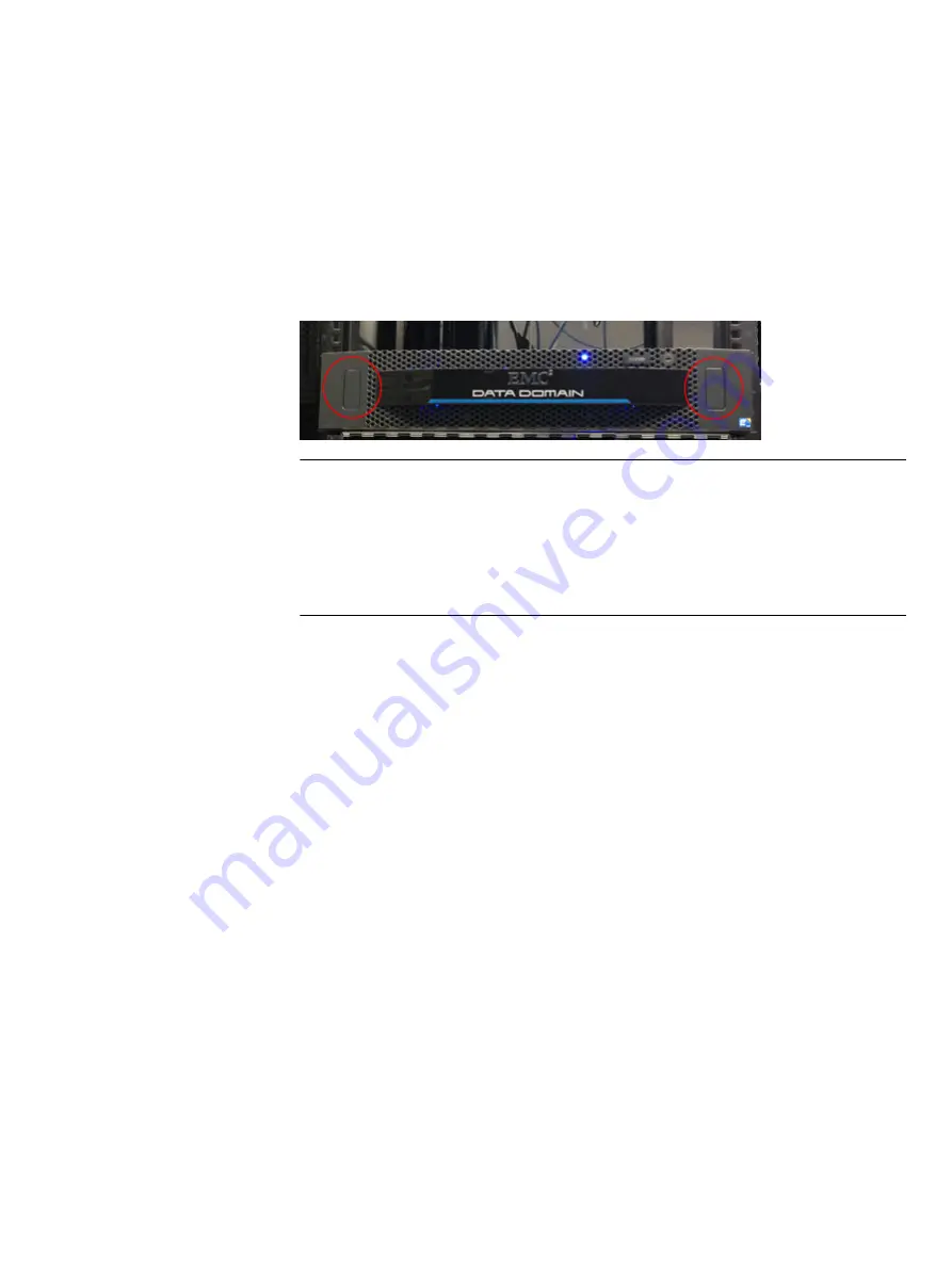
Figure 22 Front bezel
Note
l
The photo shows the bezel attached to a live system. The blue system power LED,
located above and to the right of the logo, shows through the bezel.
l
The bezel contains a lock and is shipped with a key. If desired, lock the bezel in place.
l
Push on the two handhold positions to remove the bezel as needed.
Connect data cables
1. Enable data transfer Ethernet connectivity. Repeat for each connection.
a. If using 1 Gb copper Ethernet, attach a Cat 5e or Cat 6 copper Ethernet cable to an
RJ-45 Ethernet network port (start with ethMa and go up).
b. If using 1 Gb fiber Ethernet, use multimode fiber cables with LC connectors.
c. If using 10 Gb copper Ethernet with an SFP+ connector, use a qualified SFP+
copper cable.
d. If using 10 Gb fiber Ethernet, use MMF-850nm cables with LC duplex connectors.
e. For 10GBaseT connections, use Cat6a S-STP Ethernet cables.
2. Enable data transfer Fibre Channel (FC) connectivity. Repeat for each connection.
a. Attach a Fibre Channel fiber optical cable (LC connector) to an I/O module port on
the controller, and attach the other end (LC connector) to an FC switch or to an FC
port on your server.
Powering on the controller
1. Connect the power cables to each receptacle, and attach the retention clips. The
system immediately powers on when plugged in.
2. Ensure that each power supply is connected to a different power source. Note that:
l
A new BBU may take up to three hours to charge to a sufficient level before the file
system is enabled.
EMC Data Domain DD2500 System Installation and Setup Guide
Install the bezel
19


