Chapter 2: Checking Out Your Computer
8
Back
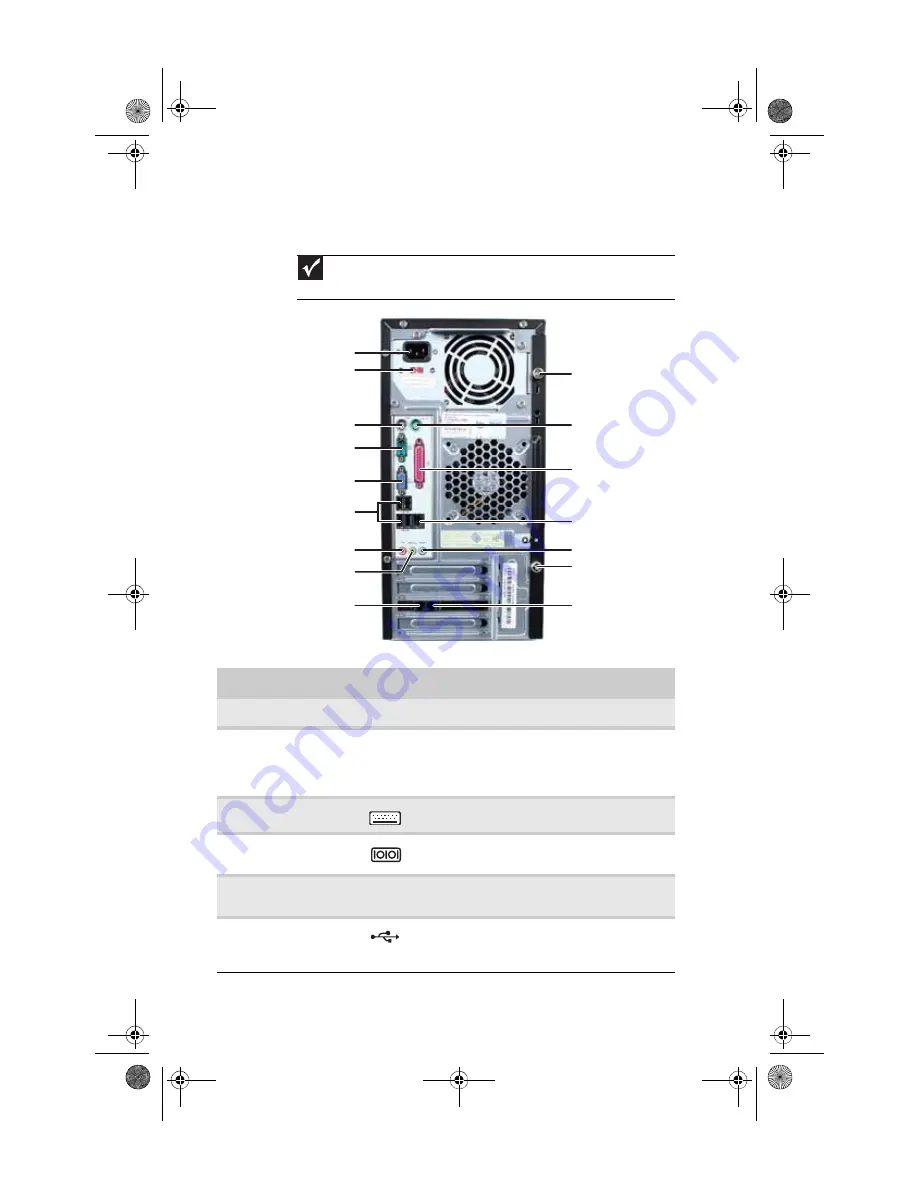
Important
Your computer’s hardware options and port locations may vary from this
illustration.
Component
Icon
Description
Power connector
Plug the power cord into this connector.
Voltage switch
The switch is preset at the factory. Make
sure that this is set to the correct voltage for
your area. For more information, see
“Checking the voltage selection” on page 15
PS/2 keyboard port
Plug a PS/2 keyboard into this port.
Serial port
Plug a serial device (such as a digital
camera) into this port.
Monitor (VGA) port
Plug a VGA (blue connector) monitor cable
into this port.
USB ports
Plug USB (Universal Serial Bus) devices
(such as a USB printer, scanner, camera,
keyboard, or mouse) into these ports.
Telephone jack (optional)
PS/2 mouse port
PS/2 keyboard port
Voltage switch
Power connector
Ethernet (network) jack
Case thumbscrew
Headphone/speaker jack
Microphone jack
USB ports
Modem (line) jack
(optional)
Case cover thumbscrew
Parallel port
Monitor (VGA) port
Serial port
Audio in jack
8513152.book Page 8 Wednesday, May 14, 2008 4:57 PM
Summary of Contents for 8513152
Page 1: ...Computer Reference Guide 8513152 book Page a Wednesday May 14 2008 4 57 PM...
Page 2: ...8513152 book Page b Wednesday May 14 2008 4 57 PM...
Page 10: ...Chapter 1 About This Reference 4 8513152 book Page 4 Wednesday May 14 2008 4 57 PM...
Page 16: ...Chapter 2 Checking Out Your Computer 10 8513152 book Page 10 Wednesday May 14 2008 4 57 PM...
Page 76: ...Chapter 5 Maintaining Your Computer 70 8513152 book Page 70 Wednesday May 14 2008 4 57 PM...
Page 114: ...Appendix A Legal Notices 108 8513152 book Page 108 Wednesday May 14 2008 4 57 PM...
Page 123: ...8513152 book Page 117 Wednesday May 14 2008 4 57 PM...
Page 124: ...MAN ECOOPER EREC REF GDE R0 5 08 8513152 book Page 118 Wednesday May 14 2008 4 57 PM...


