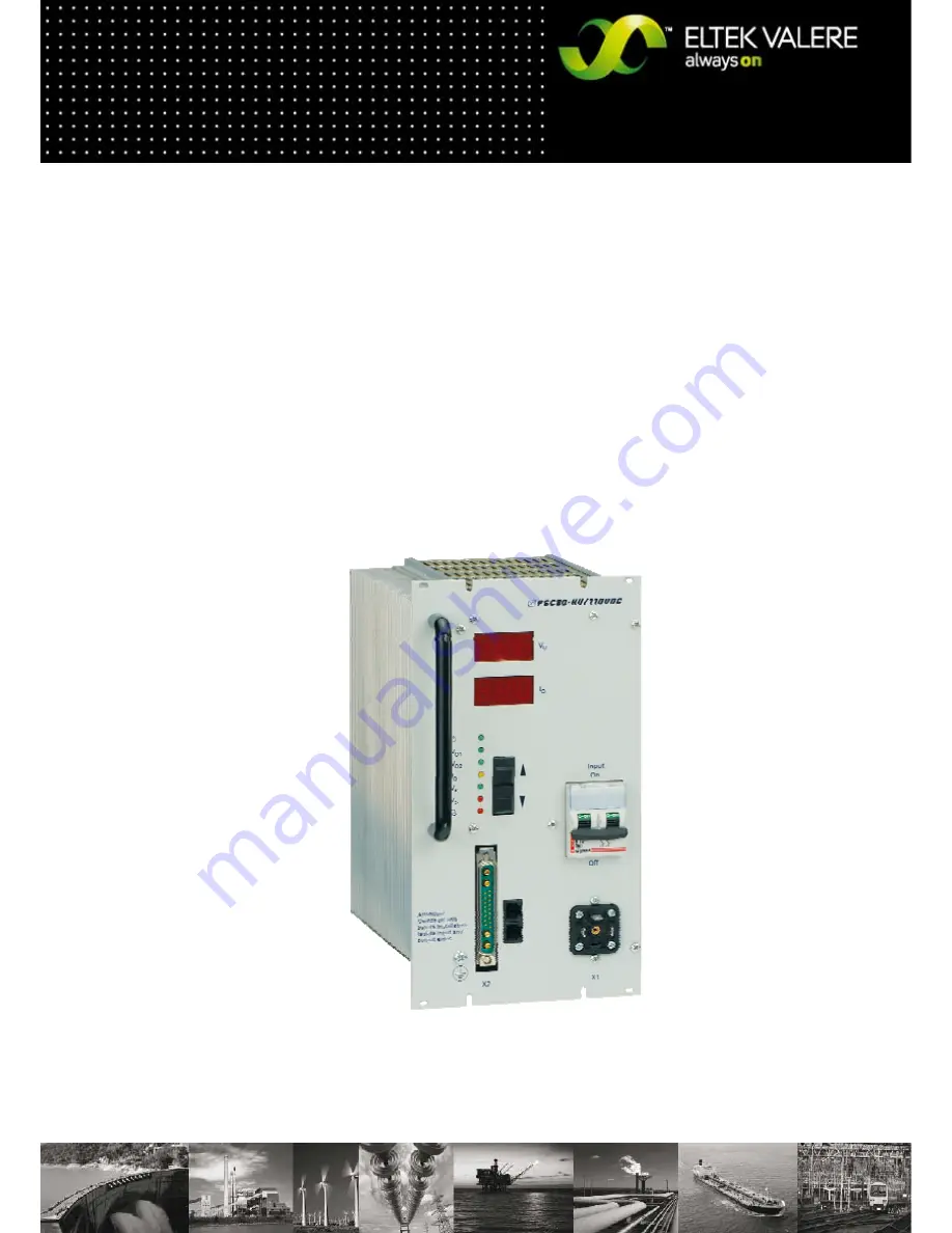
DC/DC Converter
PSC30
User Manual
UM_PSC30_E_EVD_2011-01-19.doc
Page 1: ...DC DC Converter PSC30 User Manual UM_PSC30_E_EVD_2011 01 19 doc...
Page 2: ...here are no obligations to update the manual continually The module is manufactured in accordance with applicable DIN and VDE standards such as VDE 0106 part 100 and VDE 0100 part 410 The CE marking o...
Page 3: ...overheating 9 5 3 6 Signals 9 5 4 Output and threshold adjustment 10 5 4 1 Adjustable parameters at the adjustment mode 10 6 EXTERNAL FUNCTIONS 11 6 1 Output voltage sensor leads 11 6 2 Temperature c...
Page 4: ...3 It is a ready for con nection unit for integration in a 19 sub rack according to DIN 41494 All operation and indication elements as well as the plugs are located at the front plate of the unit 2 Typ...
Page 5: ...cted at the output If the SMPS output in the dead state is connected hard to a battery or other parallel operating SMPS then it results in a considerable surge of charging current which could lead in...
Page 6: ...DC DC Converter PSC30 User Manual Page 6 24 2009 ELTEK VALERE DEUTSCHLAND GmbH UM_PSC30_E_EVD_2011 01 19 doc 5 Functions 5 1 Circuit diagram Fig 1 Circuit diagram PSC30...
Page 7: ...r to the potential separation and voltage adaptation at the secondary side 5 Rectifier with fast switching diodes 6 LC filter for smoothing the DC voltage ripple at the rectifier output 7 Output filte...
Page 8: ...eristic curve factory set a load distribution of about 10 and due to the optional active current distribution see section 7 3 factory adjustment necessary about 5 is attained During the adjustment of...
Page 9: ...higher than adjusted level V This signal is included in collective failure signal It has its own relay contact on signaling connector too If the voltage value is okay Pin 13 and Pin 17 of X2 or Pin 1...
Page 10: ...ustment value if you hold the key the value changes quicker press both keys UP DOWN together for a short time the SMPS changes back to adjust ment mode at this moment the changed value will be storage...
Page 11: ...with connection of the shield to modules ground 6 3 External switch ON OFF The SMPS can be switched on off by an external signal The input is potential free due to an opto coupler and fulfills the req...
Page 12: ...elements 24 48 60 110 V version Digital display for output voltage and current indication of the parameters and related values in the adjustment mode LED indicators Adjustment keys UP and DOWN Input s...
Page 13: ...w operation elements 220 V version Digital display for output voltage and current indication of the parameters and related values in the adjustment mode LED indications Adjustment keys UP and DOWN Inp...
Page 14: ...SC30 Vin 110VDC Pin 4 must be connected to plus DC input according to the table above due to the higher input current The PE connection bolt M4 is available at the front plate of the module see pictur...
Page 15: ...of each unit have to be inter connected 3 At active current sharing mode of paralleled units all pin 8 of each module have to be intercon nected The analog GND pin 10 has to be interconnected too ATTE...
Page 16: ...ON 1 5mm2 Pin assignment of X4 for PSC30 220V with signalling relay without CAN Bus Pin Function 1 external switch ON OFF 4 2 external switch ON OFF 3 Opto coupler emitter 4 Opto coupler collector Mai...
Page 17: ...be connected too ATTENTION If active current sharing mode is enabled the use of external decoupling diodes and fuses as well in minus on the output side are not allowed 4 External switch ON Off with...
Page 18: ...oltage Is the DC input voltage present Is the DC input switch in on position Is the input plug correctly connected Is the polarity correct or short circuit at the output Paralleled units incorrect pol...
Page 19: ...HF field acc EN61000 4 part 3 10V m 30Mhz 1GHz power wires Burst test acc EN61000 4 part 4 2kV Surge test acc EN61000 4 part 5 4kV unsymmetric 2kV symmetric signal wires Burst Test acc EN61000 4 part...
Page 20: ...V K per cell adjustable with external sensor optional external sense links for output voltage signaling with optocouppler VO O K Mains O K and Iconst external switch ON OFF function Operation in paral...
Page 21: ...9 ELTEK VALERE DEUTSCHLAND GmbH UM_PSC30_E_EVD_2011 01 19 doc DC connector X2 24 110V DC SUB Min D connector 21WA4 220V DC front terminals 8 x 4mm2 COMBICON DC output front terminals 15 x 1 5mm2 signa...
Page 22: ...48 to 60 72 0 1 60 to 73 129 6 1 110 to 135 259 2 1 220 to 270 Output voltage VO3 in V DC discharge test Adjusted value 22 2 1 Adjusting range 20 4 bis 24 44 4 1 40 8 to 48 55 5 1 51 to 60 99 9 1 91...
Page 23: ...DC DC Converter PSC30 User Manual Page 23 24 2009 ELTEK VALERE DEUTSCHLAND GmbH UM_PSC30_E_EVD_2011 01 19 doc 10 3 Dimensions front view 24 to 110V...
Page 24: ...DC DC Converter PSC30 User Manual Page 24 24 2009 ELTEK VALERE DEUTSCHLAND GmbH UM_PSC30_E_EVD_2011 01 19 doc 10 4 Dimensions front view 220V...