background image

6

Installation and start-up

Radio Actuator KNX RF S1R-B2 compact

 • Version: 16.09.2020 • Technical changes and errors excepted.

2.4. Connection

The 

Radio Actuator KNX RF S1R-B2 compact

 is installed in a flush-mounted sock-

et. 

The connection to the 

KNX data bus

 is made via radio (KNX RF). The device is inte-

grated into the KNX system via a KNX RF USB stick or via a media coupler (refer to the
relevant manual/data sheet).

Connect the 

operating voltage

 (230 V AC, 50 Hz) to the “Power IN“ L/N terminals.

Connect 

the drive or the loads

 to the “OUT“ U

A

/A1/A2 terminals. The output is free

of potential and supplied with voltage U

A

To connect the 

digital inputs

 (fig. 1 no. 1) use the attached cable. The cables for the

inputs can be extendet to up to 10 m.

Follow the guidelines and standards for SELV electric circuits 
while installing and cable laying of the inputs!

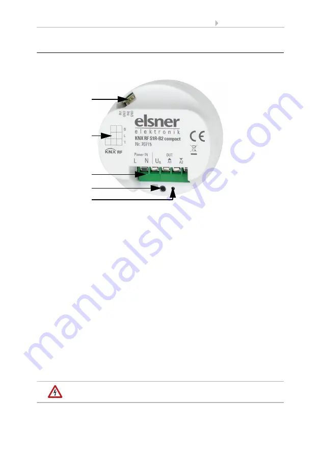
Fig. 1
1

Digital inputs: Slot for connection cable

2

Labelling field

3

Connector for operating „Power IN“ 230 V AC, 50 Hz, L/N
and for drive/consumers „OUT“(free of potential):
U

A

: voltage, maximum 270 V AC

up/A1: motor upwards or consumer 1 switching
down/A2: motor downwards or consumer 2 switching

4

Programming button (recessed)

5

Programming LED (recessed)

1

3

2

4
5

Summary of Contents for 70715

Page 1: ...EN Installation and Adjustment KNX RF S1R B2 compact Multifunctional Radio Actuator Item number 70715...

Page 2: ......

Page 3: ...uctions for assembly and operational start up 8 3 Addressing of the device at the bus 8 4 Disposal 9 5 Transfer protocol 10 5 1 List of all communication objects 10 6 Parameter setting 14 6 1 General...

Page 4: ...eshooting of the device must only be carried out by a competent electrician Safety advice Safety advice for working on electrical connections components etc DANGER indicates an immediately hazardous s...

Page 5: ...light fan 2 binary inputs Position feedback movement position also slat position for shutters Position storage movement position via 1 bit object storage and call up e g via buttons Parameters for ta...

Page 6: ...The device is only to be used for the intended purpose described in this manual Any improper modification or failure to follow the operating instructions voids any and all warranty and guarantee claim...

Page 7: ...the power supply is removed the connected drive switches off When the power is restored the consumer remains switched off until a new movement command is re ceived by the actuator WARNING Risk of inju...

Page 8: ...drive or the loads to the OUT UA A1 A2 terminals The output is free of potential and supplied with voltage UA To connect the digital inputs fig 1 no 1 use the attached cable The cables for the inputs...

Page 9: ...nical changes and errors excepted 2 4 1 Connection examples output Fig 2 Breakout cable for digital inputs Input 1 black white GND Input 2 yellow violet GND Drive 230 V AC Mains 230 V AC Two consumer...

Page 10: ...ing this phase no information can be received or sent via the bus For KNX devices with safety functions e g wind or rain blocks it is important to set up periodical monitoring of the safety objects Th...

Page 11: ...X RF S1R B2 compact Version 16 09 2020 Technical changes and errors excepted 4 Disposal After use the device must be disposed of or recycled in accordance with the legal reg ulations Do not dispose of...

Page 12: ...1 Bit 107 Automatic movement position Input RWC 5 1 DPT_Scaling 1 Byte 108 Automatic blind position Input RWC 5 1 DPT_Scaling 1 Byte 109 Change from manual to automatic mode Input RWC 1 1 DPT_Switch 1...

Page 13: ...status Output R CT 1 1 DPT_Switch 1 Bit 189 Block 2 Rain blocking object Input RWC 1 1 DPT_Switch 1 Bit 190 Block 3 Blocking object Input RWC 1 1 DPT_Switch 1 Bit 191 Block 3 Wind blocking object Inp...

Page 14: ...ht function Input RWC 1 10 DPT_Start 1 Bit 217 Channel A1 Link Input RWC 1 2 DPT_Bool 1 Bit 218 Channel A1 Call up saving scenes Input RWC 18 1 DPT_SceneControl 1 Byte 220 Channel A2 Switch Input RWC...

Page 15: ...260 Input 2 Extended Input Output RWCT 1 8 DPT_UpDown 1 Bit 261 Input 2 Short Output R CT 1 8 DPT_UpDown 1 Bit 262 Input 2 Switch Input Output RWCT 1 1 DPT_Switch 1 Bit 263 Input 2 Relative dimming In...

Page 16: ...fications for the connected drive see Channel settings drives page 15 Control functions Movement range limit blocking type of automatic see Control drives page 17 Scenes Movement positions see Scenes...

Page 17: ...between the end positions is the basis for moving into intermediate positions e g for movement range limits and scenes You can enter the runtime numerically in seconds or have the runtime determined...

Page 18: ...rive should be adjusted according to the specifications of the motor manufacturer Reference movement With the regular movement to the two end positions the runtime and zero position are adjusted again...

Page 19: ...t to open One of two drive mechanisms is prioritised and is parameterised as master and the other one as slave By means of zero position sensors both actuators know the own current status and the curr...

Page 20: ...the window shall be opened The window knows the status of the awning not safe position and therefore submits a master command to the awning This is the signal for the awning to retract a little bit A...

Page 21: ...red in their own menu items See Movement limits on Page 30 Use Block 1 high priority no yes with blocking object yes as wind blocking yes as rain blocking Use block 2 no yes with blocking object yes a...

Page 22: ...ches in conference rooms Here it is also specified in which mode the channel is found when the voltage returns i e after a power failure The mode manual or automatic is send as a status object to the...

Page 23: ...t wind blocking is linked with the output object of a wind sensor The input can be a 1bit object smaller or larger than a threshold value as well as a 16bit object measurement value Designation Block...

Page 24: ...0 Slat position in only if by using a block a specific shutter position is achieved 0 100 Waiting period in secure position in min after blocking 0 255 5 Behaviour after waiting period For manual oper...

Page 25: ...ose command open command window Position in only if by using a block a specific position is achieved 0 100 Slat position in only if by using a block a specific shutter position is achieved 0 100 Waiti...

Page 26: ...actuator is linked to this group address A scene is called then the scene number is communicated to the actuator The movement position saved for this scene number in the actuator is then taken If the...

Page 27: ...quently needed bus functions Thus the inputs can easily be configured as a switch drive control dimmer for sending values and for the scene calls Input as switch If a button with switch function is as...

Page 28: ...shutter blinds awning or window control If the input to the drive control is used via the bus select the bus function shutter awning blinds or window and specify the button function and control mode S...

Page 29: ...ocking object For active blocking there is no bus communication Input 8 bit encoder If the input is to be used as an 8bit encoder select the 8 bit encoder bus function and specify which value will be...

Page 30: ...used as a brightness encoder e g threshold value of a sun sensor select brightness encoder and specify which value will be sent The input can be blocked using a blocking object For active blocking th...

Page 31: ...tuating the button briefly a bit longer and long will trigger different responses of the drive The time intervals are set individually Short actuation shorter than Time 1 The drive is positioned step...

Page 32: ...nctions page 30 Point in time 0 Actuate of button start of time 1 Release before time 1 expired step or stop if drive is moving Point in time 1 End of time 1 start of time 2 Moving command Release aft...

Page 33: ...inutes The switch off delay effects that the ventilator will follow up if the button was operated again and the light is already off The staircase timer function makes sure for example that the light...

Page 34: ...ings for the switch function channel if selected Use blocking functions Yes The output channel can be blocked by a block telegram What happens during the blocking for bus voltage return and after the...

Page 35: ...ire alarm blocking When switching via communication object Channel A1 switch 210 the light is turned on or off normally When switching via object Channel A1 staircase light function start 215 the stai...

Page 36: ...bH Control and Automation Engineering Sohlengrund 16 75395 Ostelsheim Phone 49 0 70 33 30 945 0 info elsner elektronik de Germany Fax 49 0 70 33 30 945 20 www elsner elektronik de Technical support 49...

Reviews: