


Chapter Three
Operation
Man_805U Rev 1.8
Page
15
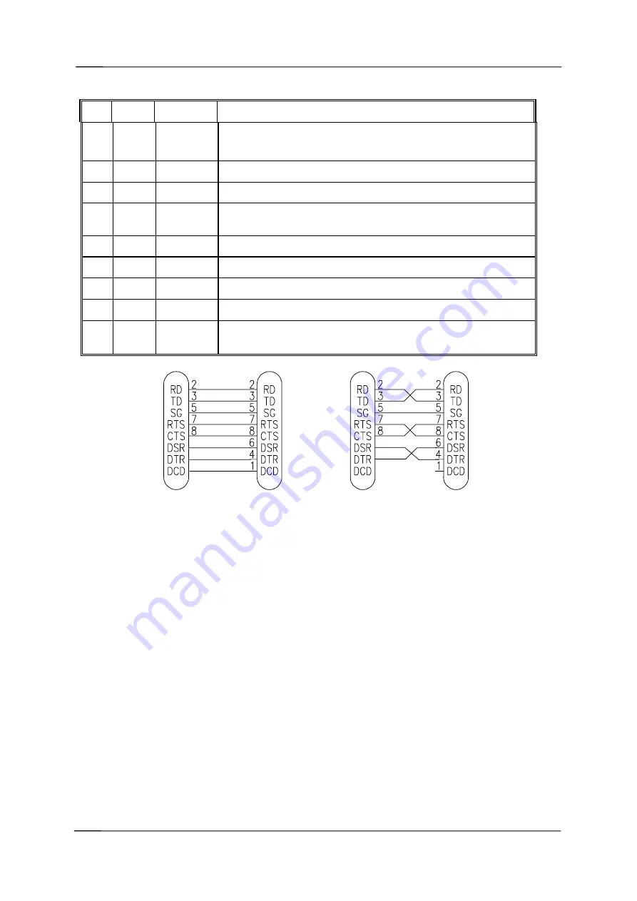
DB9 Connector Pinout
Pin
Name
Direction
Function
1
DCD
Out
Data carrier detect
–
- driven when link is established in controlled mode
- driven always in transparent mode
2
RD
Out
Transmit Data
– Serial Data Output
3
TD
In
Receive Data
– Serial Data Input
4
DTR
In
Data Terminal Ready
- DTR can be configured to initiate low power
mode, or to force a link disconnection (“hang up” in controlled mode.
5
SG
Signal Ground
6
DSR
Out
Data Set Ready
- always high when unit is powered on.
7
RTS
In
Request to Send -
hardware flow control configurable
8
CTS
Out
Clear to send -
hardware flow control configurable
9
RI
Ring indicator
- indicates another module is attempting to connect in
controlled mode.
805U
DB9
MALE
DTE HOST
DB9
FEMALE
805U
DB9
MALE
DCE HOST
DB9
MALE
2.4.2 RS485 Serial Port
The RS485 port provides for communication between the 805U unit and its host device using a
multi-drop cable. Up to 32 devices may be connected in each multi-drop network. Note that
the RS485 port is shared internally with the RS232 port - make sure that the RS232 port is
disconnected before using the RS485 port.
As the RS485 communication medium is shared, only one of the units on the RS485 cable
may send data at any one time. Thus communication protocols based on the RS-485
standard require some type of arbitration.
RS485 is a balanced, differential standard but it is recommended that shielded, twisted pair
cable be used to interconnect modules to reduce potential RFI. It is important to maintain the
polarity of the two RS485 wires. An RS485 network should be wired as indicated in the
diagram below and terminated at each end of the network with a 120 ohm resistor. On-board
120 ohm resistors are provided and may be engaged by operating the single DIP switch in the
end plate next to the RS485 terminals. The DIP switch should be in the “1” or “on” position
to connect the resistor. If the module is not at one end of the RS485 cable, the switch should
be off.


