Art.-Nr./Art. No./Réf./N° art/N° art.: 9010007B01M
Version: 1.2
Date:
21.03.2017
2/
6
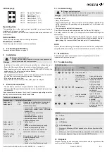
LED displays
Operating time
The operating time is the maximum time permitted on a sensor between
actuation of both sensor contacts.
With 2-hand operation, it is the maximum time permitted between actuation of
both sensors.
Safe condition
The safety outputs are opened or with high resistance.
Hazardous condition
The safety outputs are closed or with low resistance.
7
Technical specifications
See technical specifications on page 13.
8
Installation
- Installation of the safety control unit is only permitted in a voltage-free state.
- Ensure that the required fuses (see technical specifications) are used.
- Snap the safety control unit onto a mounting rail (DIN EN 60715 TH35) in the
switch cabinet. The safety control unit is attached.
- Connect the safety control unit.
The pluggable terminal blocks can be coded by means of pins, the sockets
in the device are inversely coded by means of coding tabs
- If the safety input remains free:
Ensure that the contact makers of this safety input are bridged.
9
Electrical connection
- The electrical connection is only permitted in a voltage-free state.
- Make sure that the specifications described in the technical data are always
complied with.
Upon connection of a sensor, the (+) and (-) sensor supply voltage must be
used by the terminals stated in the technical data.
Terminal connections
Danger
Danger of electrocution!
Ensure that the safety control unit is only put into operation by
specially-trained authorised personnel.
Components
Terminal/s Description
Safety input 1
5-8
Depending on configuration, the inputs at
terminals 8, 12 are (+) or (-) read-only.
Connection options:
- sensors with 2 contact maker (NO) system
- sensors with contact maker (NO)/contact
breaker (NC)
- Emergency-Stop push-button
- two-hand control
- photoelectric sensor (OSSD)
- photoelectric sensor (OSSD)
Safety input 2
9-12
Safety output 1
4, 16
Switching dependent on:
- Safety input 1-2
- Logic
- Switch on/switch off delay (optional)
- Switch on/start inputs (optional)
Safety output 2
3, 15
External contactor/
start
2
External contactor and/or start button
(automatic, manual or monitoring)
Operating voltage
1, 13
Control output
14
Not suitable for safety functions!
Switching dependent on:
- Safety input 1-2
- Logic
- Switch on/switch off delay (optional)
1
3
5
4
6
2
LED 1
Operability ("Ready")
LED 2
Fault ("Error")
LED 3
Safety input 1 ("I 1")
LED 4
Safety input 2 ("I 2")
LED 5
Safety output 1 ("O 1")
LED 6
Safety output 2 ("O 2")
10 Commissioning
In arbitrary order:
-
-
Damp safety sensors.
Apply operating voltage - make sure that no external voltage is applied to the
safety inputs when the operating voltage is applied (e.g. by devices with
OSSD outputs).
- Then actuate the start button if necessary.
The LEDs of the inputs and outputs used and the "Ready" LED light up.
The safety control unit is ready. The safety control unit switches through the
safety output.
- If the ready LED and the LEDs of for the applied inputs are lit up, the outputs
flash and the error LED is off, then the safety control unit is waiting for the start
signal at input "ext. contactor/Start" (see also point 12 Troubleshooting).
NOTE
Upon initial commissioning of a safety control unit with a new configuration,
complete validation according to the relevant standards must be carried out.
11 Maintenance
The switching behaviour and sequences of every safety circuit must be
inspected at least once per year.
12 Troubleshooting
Danger
Danger of electrocution!
Ensure that the safety control unit is only put into operation by
specially-trained authorised personnel.
LEDs eloFlex Mini
Meaning
Remedy
Re
ady
Error
I1
I2
O1
O2
Normal operation
—
Operating time
exceeded, only
affected input(s) will
flash
Open and close the
door. If error persists,
replace the sensor/
switching device.
Internal fault
Apply the supply
voltage again. If error
persists, replace the
control unit.
1
1
Input(s) available,
start expected
Check the feedback
loop: Is the start
signal at the input
start 1 (terminal 1/2)
available?
Internal fault
Apply the supply
voltage again. If error
persists, replace the
control unit.
13 Disposal
Dispose of packaging and used parts in accordance with the regulations of the
country in which the device is installed.
Legend
LED on
LED off
LED flashes
LED arbitrary state
Number of lit/flashing LEDs is dependent on the configuration of the
eloFlex.
Make sure that no external voltage is applied to the safety inputs
during a voltage reset (e.g. by devices with OSSD outputs).
1
2


