background image


Elo Touch Solutions | 670 N. McCarthy Blvd., Suite 100 | Milpitas, CA 

95035

 | 800 ELO TOUCH | +1 408 597 8000 | www.elotouch.com 

CAN ICES3(B)/NMB3(B) 
 

T


c  c


 I

 Ca a a   c

-exempt RSSs. Operation is subject to the 

following two conditions: 
(1) This device may not cause interference; and   
(2) This device must accept any interference, including interference that may cause undesired 
operation of the device.


L  

 a a


 c

 a  CNR  I

 Ca a a a

cab

 a  a a

  a


    c

c . L

a


 a

 a  

 c


a

 :


(1)  a a


oit pas produire de brouillage;et 

(2) 

a

    a a


 acc


 b

a   a

c

  b , 


b

a  


c

b  

 c


c

.


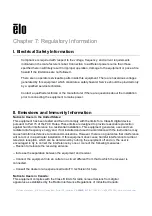
Notice to Users in the European Union

: Use only the provided power cords and 

interconnecting cabling provided with the equipment. Substitution of provided cords and cabling 
may compromise electrical safety or CE Mark Certification for emissions or immunity as 
required by the following standards: 

This Information Technology Equipment (ITE) is required to have a CE Mark on the 
Manufacturer s label which means that the equipment has been tested to the following 
Directives and Standards: This equipment has been tested to the requirements for the CE Mark 
as required by EMC Directive 2014/30/EU as indicated in European Standard EN 55032 Class 
B and the Low Voltage Directive 2014/35/EU as indicated in European Standard EN 60950-1. 

General Information to all Users

: This equipment generates, uses and can radiate radio 

frequency energy. If not installed and used according to this manual the equipment may cause 
interference with radio and television communications. There is, however, no guarantee that 
interference will not occur in any particular installation due to site-specific factors. 

1) In order to meet emission and immunity requirements, the user must observe the following: 

a) Use only the provided I/O cables to connect this digital device with any computer. 

b) To ensure compliance, use only the provided manufacturer s approved line cord. 

c) The user is cautioned that changes or modifications to the equipment not expressly 
approved by the party responsible for compliance could void the user s authority to operate 
the equipment. 

2) If this equipment appears to cause interference with radio or television reception, or any 
other device: 

Summary of Contents for ET1517L

Page 1: ...Elo Touch Solutions 670 N McCarthy Blvd Suite 100 Milpitas CA 95035 800 ELO TOUCH 1 408 597 8000 www elotouch com USER MANUAL Elo Touch Solutions ET1517L and ET1717L Touchmonitors SW601708 Rev G ...

Page 2: ... this document is subject to change without notice Elo Touch Solutions Inc and its Affiliates collectively Elo makes no representations or warranties with respect to the contents herein and specifically disclaims any implied warranties of merchantability or fitness for a particular purpose Elo reserves the right to revise this publication and to make changes from time to time in the content hereof...

Page 3: ...UCH 1 408 597 8000 www elotouch com Table of Contents Chapter 1 Introduction 4 Chapter 2 Installation 5 Chapter 3 Mounting 7 Chapter 4 Operation 13 Chapter 5 Technical Support 18 Chapter 6 Safety Maintenance 20 Chapter 7 Regulatory Information 22 Chapter 8 Warranty Information 28 ...

Page 4: ...y display performance Its LED backlight significantly reduces power consumption and eliminates mercury compared to CCFL backlit panels Other features that a c LCD a c a e Plug Play compatibility on screen display OSD controls and an optional magnetic stripe reader MSR Precautions Follow all warnings precautions and maintenance as recommended in this user manual to maximize the life of your unit to...

Page 5: ...uchmonitor Open the carton and verify that the following items are present x Touchmonitor with protective sheet over touchscreen x User Manuals CD x Japanese language regulatory information pamphlet x Quick Install Guide x VGA cable x USB cable x North American power cable x European power cable x Filler plate White or Black depends on the monitor color ...

Page 6: ... touch cab b USB serial connector and your PC USB serial port 3 Select the correct power cable for your region Connect the power cable between the AC power source and the AC input power jack 4 Alternatively if you have purchased an optional power adapter and elected to use it connect the cable between the AC power source and the optional a a c c C c a a DC c c DC input power jack 5 The touchmonito...

Page 7: ... computer No additional drivers are required for your projected capacitive touchmonitor it uses Windows HID drivers To download latest touch drivers 1 Visit www elotouch com Support Downloads Driver DriverDownload Default aspx 2 S c a O a S 3 S c c T c ropdown menu 4 Click on the driver version required for your touchmonitor 5 C c Acc c a c D L c A a 6 E a a C c N S Y a a a a ca 7 If you are a a a...

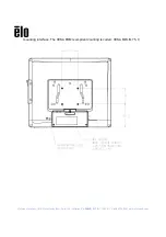
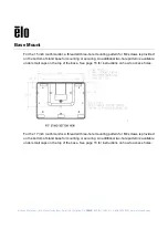
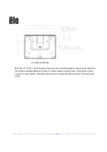
Page 8: ...x75mm mounting pattern for M4 screws is provided on the rear of the monitor Remove the stand using a Phillips screwdriver to access this mounting interface The VESA FDMI compliant counting is coded VESA MIS B 75 C For the 17 inch touchmonitor a four hole 75x75mm mounting pattern for M4 screws is provided on the rear of the monitor Remove the stand using a Phillips screwdriver to access this ...

Page 9: ...Elo Touch Solutions 670 N McCarthy Blvd Suite 100 Milpitas CA 95035 800 ELO TOUCH 1 408 597 8000 www elotouch com mounting interface The VESA FDMI compliant counting is coded VESA MIS B 75 C ...

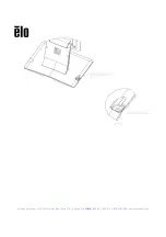
Page 10: ...se for mounting or securing An additional two hole pattern is available under small caps on the top of the base See page 15 for instructions on how to access holes For the 17 inch touchmonitor a threaded three hole mounting pattern for M4 screws is provided on the bottom of stand base for mounting or securing An additional two hole pattern is available under small caps on the top of the base See p...

Page 11: ...408 597 8000 www elotouch com B 15 a 17 c s have covered mounting holes for securing the stand to a flat surface using M4 flathead screws To utilize these mounting holes unsnap the access covers from the outside install the screws into the holes and then snap the cover back into place ...

Page 12: ...Elo Touch Solutions 670 N McCarthy Blvd Suite 100 Milpitas CA 95035 800 ELO TOUCH 1 408 597 8000 www elotouch com ...

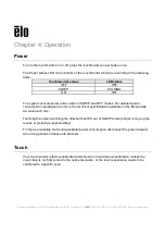
Page 13: ... and OFF modes For detailed power consumption specifications refer to the technical specifications available on the Elo website www elotouch com Touching the screen will bring the attached host PC out of SLEEP mode similar to moving the mouse or pressing a keyboard key To improve reliability and reduce wasteful power consumption disconnect the power adapter when long periods of disuse are planned ...

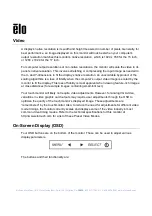
Page 14: ...to fit the display This loss of fidelity is most apparent when viewing feature rich images at close distances for example images containing small font text Your touchmonitor will likely not require video adjustments However for analog VGA video variations in video graphic card outputs may require user adjustments through the OSD to optimize the quality of the touchmonitor ayed image These adjustme...

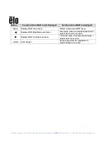
Page 15: ...splayed Function when OSD is displayed Menu Display OSD main menu Return to previous OSD menu Display OSD Brightness submenu Decrease value of selected parameter select previous menu item Display OSD Contrast submenu Increase value of selected parameter select next menu item Select Auto Adjust Select parameter for adjustment select submenu to enter ...

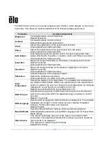
Page 16: ...entered Only applicable for VGA input video Sharpness Adjusts sharpness of the displayed images Default No sharpness adjustment Only applicable at non native input video resolutions Color Temperature S c a c a T a a ab c a are 9300K 7500K 6500K 5500K and User Defined If the User Defined option is selected the user can change the color temperature by changing individual R G and B gains on a scale f...

Page 17: ...s every time the touchmonitor is unplugged or powered off and on If there is a power failure the touchmonitor settings will not default to the factory specifications OSD and Power Lockouts P a M a D b c ab ab OSD Locking feature When the OSD Locking is enabled pressing any of the Menu Up Down or Select keys will have no effect on the system Pre a M a U b c ab ab P Locking feature When the Power Lo...

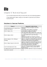
Page 18: ...the contrast Monitor display is blank If the Power Status LED is blinking the monitor may be in SLEEP mode Press any key move the mouse touch the Touchscreen to see if the image reappears Check that the signal source device is turned on Check that that there are no loose cable connections M a a O O Ra message A c b within the allowable timing ranges specified for your touchmonitor see website for ...

Page 19: ...O TOUCH 1 408 597 8000 www elotouch com Technical Assistance Visit www elotouch com products for technical specifications for this device Visit www elotouch com go websupport for online self help Visit www elotouch com go contactsupport for technical support S a a a a c ca b ...

Page 20: ...uchmonitor functioning at an optimal level x Disconnect the AC power cable before cleaning x To clean the display unit cabinet use a clean cloth lightly dampened with a mild detergent x It is important that your unit remains dry Do not get liquids on or inside the unit If liquid does get inside have a qualified service technician check it before you power it on again x Do not wipe the screen with ...

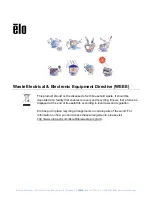
Page 21: ...disposed of with household waste It should be deposited at a facility that enables recovery and recycling Ensure that product is disposed at the end of its useful life according to local laws and regulation Elo has put in place recycling arrangements in certain parts of the world For information on how you can access these arrangements please visit http www elotouch com AboutElo ewaste program ...

Page 22: ... the limits for a Class B digital device pursuant to Part 15 of the FCC Rules These limits are designed to provide reasonable protection against harmful interference in a residential installation This equipment generates uses and can radiate radio frequency energy and if not installed and used in accordance with the instructions may cause harmful interference to radio communications However there ...

Page 23: ...tives and Standards This equipment has been tested to the requirements for the CE Mark as required by EMC Directive 2014 30 EU as indicated in European Standard EN 55032 Class B and the Low Voltage Directive 2014 35 EU as indicated in European Standard EN 60950 1 General Information to all Users This equipment generates uses and can radiate radio frequency energy If not installed and used accordin...

Page 24: ...ver iii Reorient the affected receiver s antenna iv Plug the digital device into a different AC outlet so the digital device and the receiver are on different branch circuits v Disconnect and remove any I O cables that the digital device does not use Unterminated I O cables are a potential source of high RF emission levels vi Plug the digital device into only a grounded outlet receptacle Do not us...

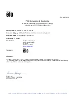
Page 25: ...lecommunications Equipment Equipment Class Commercial and Light Industrial Product Name Monitor Manufacturer Elo Touch Solutions Inc 670 N McCarthy Blvd Suite 100 Milpitas CA 95035 www elotouch com Trademark Declaration This device complies with Part 15 of the FCC Rules Operation is subject to the following two conditions 1 This device may not cause harmful interference and 2 this device must acce...

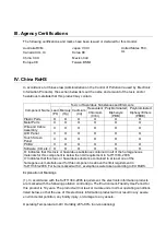
Page 26: ... O O PCBA X O O O O O Software CD etc O O O O O O O Indicates that this toxic or hazardous substance contained in all of the homogeneous materials for this component is below the limit requirement in SJ T11363 2006 X Indicates that this toxic or hazardous substance contained in at least one of the homogeneous materials used for this component is above the limit requirement in SJ T11363 2006 For it...

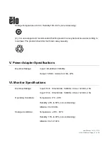
Page 27: ...asually V Power Adapter Specifications Electrical Ratings Input 100 240VAC 50 60Hz Output 12VDC minimum 4 16A LPS VI Monitor Specifications Electrical Ratings Input 1517L 100 240VAC 50 60Hz 0 3A or 12VDC 2 5A Input 1717L 100 240VAC 50 60Hz 0 5A or 12VDC 2 5A Operating Conditions Temperature 0 C 40 C Humidity 20 to 80 non condensing Altitude 0 to 3 048m Storage Conditions Temperature 20 C 60 C Humi...

Page 28: ...User Manual 1517L 1717L SW601708 Rev F Page 28 of 29 Chapter 8 Warranty Information See http www elotouch com Support warranty asp for more information ...

Page 29: ...nsive range of Elo touch solutions visit our website at www elotouch com or simply call the office nearest you North America Tel 1 408 597 8000 Fax 1 408 597 8001 customerservice elotouch com Europe Tel 32 0 16 70 45 00 Fax 32 0 16 70 45 49 elosales elotouch com Asia Pacific Tel 86 21 3329 1385 Fax 86 21 33291400 www elotouch com cn Latin America Tel 786 923 0251 Fax 305 931 0124 www elotouch com ...

Reviews: