background image

6

7

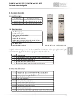
6. Geräteübersicht 

6.1 Ausführungen

Ausführung

Versorgungsspannung

ELMON rail 41-322

230V 50/60 Hz und 24 V AC/DC

ELMON rail 41-822

120V 50/60 Hz und 24V AC/DC

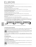
Liegt keine Fehlermeldung vor, so wird über die LED 

Power

 der Betriebszustand angezeigt (an). Bei Ausgabe 

einer Fehlermeldung gibt die Anzahl der ausgegebenen Pulse den Fehler an:

Pulse Fehlermeldung

1

Spannungsversorgung außerhalb des gültigen Wertbereiches

2

Fehler bei Testung Signaleingang

3

Ausgangssteuerung Relais gestört

4

Datenübertragung zwischen Mikrocontroller gestört

6.3 Anschlussklemmen

A1 A2

ELMON rail 41-322: Versorgungsspannung 230 V 50/60 Hz

ELMON rail 41-822: Versorgungsspannung 120 V 50/60 Hz

B1 B2

Versorgungsspannung 24 V AC/DC

X1 X2

Anschluss Signalgeber

X3 X4

Interner Abschlusswiderstand

13 14

Schaltkontakt Sicherheits-Relais 1

23 24

Schaltkontakt Sicherheits-Relais 2

31 32

Schaltkontakt Melderelais

Z1 Z2

Anschluss manuelle Rücksetzung/Wiederanlauf (Taster NO; optional)                    

Deutsch

ELMON 

rail

 41-322 / ELMON 

rail

 41-822

Sicherheitsschaltgerät

6.2 Signalanzeigen

LED 

Power

 (grün)

Betriebszustand (an)

Fehlermeldung (Pulsausgabe)

LED 

CH 1

 (rot)

Signalgeber betätigt (an)

Signalgeberstromkreis unterbrochen (blinkt schnell)

Fehlerselbsthaltung (blinkt langsam)

LED 

AUX 1

 (gelb)

Meldeausgang geschaltet

ELMON rail 41-322 ELMON rail 41-822

Summary of Contents for rail 41-322

Page 1: ...LMON rail 41 322 ELMON rail 41 822 Sicherheitsschaltgerät Operating Manual see last page for validity ELMON rail 41 322 ELMON rail 41 822 Safety Relais Manuel d utilisation Validité voir la dernière page ELMON rail 41 322 ELMON rail 41 822 Relais de sécurité Deutsch English Français Seite 3 13 ELMON rail 41 322 ELMON rail 41 822 Page 14 24 Page 25 35 ...

Page 2: ...pplémentaires Componenti ausiliari Bijkomende componenten Funktionsprüfung Functional test Contrôle de fonction Controllo funzionale Functiecontrole Sicherheitssensoren reagieren auf Betätigung Safety sensor response to actuation Le senseur de sécurité réagit à l actionnement Il sensore di sicurezza reagisce all azionamento Veiligheidssensor reageert op activering Sicherheitssensoren reagieren auf...

Page 3: ...altung manueller Reset 8 7 4 Meldeausgang unverzögert RLU 8 7 5 Meldeausgang verzögert RL 8 8 Mechanische Befestigung 9 9 Elektrischer Anschluss 9 9 1 Versorgungsspannung 9 9 2 Anschluss des Signalgebers 9 9 3 Anschluss von mehreren Signalgebern pro Signalgeberkreis 9 9 4 Anschluss Steuerstromkreise 10 9 5 Anschluss Reset 10 9 6 Anschluss Meldekontakt 10 10 Inbetriebnahme und Funktionsprüfung 11 1...

Page 4: ...ertraut sind Die Hinweise in dieser Anleitung sind unbedingt zu beachten und einzuhalten Elektrische Arbeiten dürfen nur von Elektrofachkräften durchgeführt werden Sicherheitsvorschriften der Elektrotechnik und der Berufsgenossenschaft sind zu beachten Bei Arbeiten am Schaltgerät ist dieses spannungsfrei zu schalten und auf Spannungsfreiheit zu prüfen und gegen Wiedereinschalten zu sichern Werden ...

Page 5: ... einfehlersicher und wird auch nicht durch Testung überprüft Das Schaltgerät ist nach EN ISO 13849 1 Sicherheitsbezogene Teile von Steuerungen für Kategorie 3 Performance Level e ausgelegt und baumustergeprüft Für die Einhaltung der Kategorie 3 ist der Sicherheits ausgang redundant mit zwei unabhängigen Schaltelementen aufgebaut Zusätzlich ist das Gerät nach EN 62061 Funktionale Sicherheit sicherh...

Page 6: ...estimmungsgemäßen Verwendungen entstehen übernimmt der Hersteller keine Haftung Der Einsatz bei Sonderanwendungen bedarf einer Freigabe vom Hersteller Deutsch 24V M 13 14 K2 23 24 33 34 L1 L2 L3 31 8 2ΚΩ 14 K1 24 34 13 23 33 23 13 X2 X1 B1 X4 X3 S1 32 24 14 B2 Z2 Z1 41 41 42 42 K2 K1 X1 Reset 0V Sicherheitsgerichtete Überwachung von einer Sicherheitskontaktleiste mit Startfreigabe über Freigabetas...

Page 7: ...ussklemmen A1 A2 ELMON rail 41 322 Versorgungsspannung 230 V 50 60 Hz ELMON rail 41 822 Versorgungsspannung 120 V 50 60 Hz B1 B2 Versorgungsspannung 24 V AC DC X1 X2 Anschluss Signalgeber X3 X4 Interner Abschlusswiderstand 13 14 Schaltkontakt Sicherheits Relais 1 23 24 Schaltkontakt Sicherheits Relais 2 31 32 Schaltkontakt Melderelais Z1 Z2 Anschluss manuelle Rücksetzung Wiederanlauf Taster NO opt...

Page 8: ...berstromkreis oder nach Spannungsausfall gibt das Schaltgerät den oder die Ausgänge erst wieder frei wenn die Kontakte Z1 Z2 500 ms nach Beseitigung der Störung mit einem Taster geschlossen werden Ein automatisches Wiederanlaufen ist so ausgeschlossen Ein dauerhaftes Überbrücken der Kontakte Z1 Z2 führt nicht zu einer automatischen Rücksetzung 7 4 Meldeausgang unverzögert RLU S2 ON In dieser Betri...

Page 9: ...den Anforderungen für Schutzkleinspannung SELV entsprechen Die Versorgungsleitung zum Schaltgerät ist mit einer 5x20 Glasrohrsicherung 200 mA mittelträge zu schützen Niemals beide Spannungen gleichzeitig anlegen Die 230 V 120 V Versorgungsspannung ist an die Klemmen A1 A2 anzulegen Für den Betrieb mit 24 V ist die Versorgungsspannung an den Klemmen B1 B2 anschließen Bei einer Festinstallation muss...

Page 10: ...skontaktleiste SENTIR edge Es können maximal 5 SENTIR edge in Serie geschaltet werden Die maximale Gesamtlänge der SENTIR edge darf 100 m nicht überschreiten Die Länge einer SENTIR edge kann bis zu 25 m betragen Die Gesamtleitungslänge der in Serie geschalteten SENTIR edge darf 25 m nicht überschreiten Sicherheitskontaktpuffer SENTIR bumper Es können maximal 5 SENTIR bumper in Serie geschaltet wer...

Page 11: ...dung des Signalgebers zum Schaltgerät aufgetrennt und mit einem Widerstandsmessgerät verbunden werden Bei unbetätigtem Signalgeber muss der Widerstand 8 2 kΩ 500 Ω betragen Ist der Signalgeber betätigt darf der Widerstand 500 Ω nicht überschreiten 12 Außerbetriebnahme und Entsorgung Die von ASO hergestellten Produkte sind ausschließlich für den gewerblichen Gebrauch B2B vorgesehen Nach Nutzungsbee...

Page 12: ...elträge Glasrohr 5x20 Sicherheitsrelais Max Schaltstrom 2 A 24 V AC DC Mechanische Lebensdauer 106 Betätigungen Betriebsart RL Einschaltverzögerung 0 5 Sek Betriebsart RL Einschaltdauer 3 Sek Melderelais Gehäuse Polyamid PA 6 6 selbstverlöschend nach UL 94 V2 Abmessungen HxBxT 99 x 22 5 x 114 mm Schutzart IP20 Schutzklasse II Schutzisolierung Verschmutzungsgrad 2 Überspannungskategorie III Bemessu...

Page 13: ...ung den einschlägigen grundlegenden Sicherheits und Gesundheitsanforderungen der nach folgenden EG Richtlinien entspricht EG Maschinenrichtlinie 2006 42 EG EN ISO 13849 1 2015 EN ISO 13849 2 2013 2 EN 62061 2013 09 EN 60947 5 1 2010 04 EN 61000 6 2 2005 EN 61000 6 3 2007 EG Baumusterprüfung Notified Body 0044 TÜV NORD CERT GmbH Langemarckstraße 20 D 45141 Essen EG Baumusterprüfbescheinigung Nr 44 ...

Page 14: ...ng output without any delay RLU 19 7 5 Signaling output delayed RL 19 8 Mechanical mounting 20 9 Electrical connection 20 9 1 Supply voltage 20 9 2 Connection of sensor 20 9 3 Connection of multiple sensors per sensor circuit 20 9 4 Connection of control circuits 21 9 5 Connection Reset 21 9 6 Connection of signaling contact 21 10 Commissioning and function testing 22 11 Fault diagnosis 22 12 Deco...

Page 15: ... operating instructions must be followed and adhered to unconditionally Electrical work may only be carried out by skilled electricians Safety regulations for electrical engineering and from the professional association must be followed In case work has to be carried out on the switching device it must be switched to a voltage free position and checked for freedom from any voltage and secured agai...

Page 16: ...afety orientated functions It is not fail safe and not checked by testing either The switching device has been designed and type approved in accordance with EN ISO 13849 1 Safety related parts of control systems for category 3 Performance Level e For compliance with category 3 the safety output is set up redundantly with two independent switching elements In addition the device has been type appro...

Page 17: ...accept any liability for any damage arising from use not within specifications Any use for special applications requires prior release by the manufacturer 24V M 13 14 K2 23 24 33 34 L1 L2 L3 31 8 2ΚΩ 14 K1 24 34 13 23 33 23 13 X2 X1 B1 X4 X3 S1 32 24 14 B2 Z2 Z1 41 41 42 42 K2 K1 X1 Reset 0V Safety orientated monitoring of a safety contact strip with start release via release pushbutton and separa...

Page 18: ...tween micro controllers faulty 6 3 Connection terminals A1 A2 ELMON rail 41 322 Supply voltage 230 V 50 60 Hz ELMON rail 41 822 Supply voltage 120 V 50 60 Hz B1 B2 Supply voltage 24 V AC DC X1 X2 Connection sensor X3 X4 Internal terminating resistor 13 14 Switching contact safety relay 1 23 24 Switching contact safety relay 2 31 32 Switching contact signal relay Z1 Z2 Connection manual reset re st...

Page 19: ...ircuit or after a voltage failure the switching unit will only release the output s again if the Z1 and Z2 contacts 500 ms after the elimination of the disruption are closed by means of a pushbutton This completely prevents any automatic re start A permanent bridging of the Z1 and Z2 contacts does not cause an automatic reset 7 4 Signaling output without any delay RLU S2 ON In this mode of operati...

Page 20: ...a supply with 24 V AC DC the voltage must correspond to the requirements for protective low voltages SELV The supply line to the switching device must be protected by means of a 5x20 glass tube fuse 200mA medium time lag Never apply both voltages simultaneously The 230 V 120 V supply voltage must be applied to the A1 and A2 terminals For operation with 24 V the supply voltage must be applied to th...

Page 21: ...s 24V The switching of low voltages 230V is not permissible Safety contact edge SENTIR edge A maximum of 5 SENTIR edge devices can be connected in series The maximum total length of the SENTIR edge must not exceed 100 m The length of a SENTIR edge can be up to 25 m The total line length of the series connected SENTIR edge must not exceed 25 m Safety contact bumper SENTIR bumper A maximum of 5 SENT...

Page 22: ...means of an ohmmeter For this purpose the connection of the sensor to the switching device must be separated and connected by means of an ohmmeter In the case of a non operated sensor the resistance must be 8 2 kΩ 500 Ω If the sensor is operated the resistance must not exceed 500 Ω 12 Decommissioning and disposal The products manufactured by ASO are exclusively intended for commercial use B2B At t...

Page 23: ...on 1A middle time lag fuse glass tube 5x20 Safety relay Max switching current 2 A 24 V AC DC Mechanical service life 106 operations Operating mode RL Switch on delay 0 5 Sek Operating mode RL Switch on duration 3 sec Signal relay Housing Polyamide PA 6 6 Self extinguishing according to UL 94 V2 Dimensions HxWxD 99 x 22 5 x 114 mm Protection type IP20 Protection class II protective insulation Pollu...

Page 24: ...ult of its conception and construction as well as the design we put on the market Machine Directive 2006 42 EC EN ISO 13849 1 2015 EN ISO 13849 2 2013 2 EN 62061 2013 09 EN 60947 5 1 2010 04 EN 61000 6 2 2005 EN 61000 6 3 2007 EC type approval Notified Body 0044 TÜV NORD CERT GmbH Langemarckstraße 20 D 45141 Essen EC type examination no 44 205 13031827 This declaration of conformity does not absol...

Page 25: ...tie de signal à action instantanée RLU 30 7 5 Signal de sortie ralenti RL 30 8 Fixation mécanique 31 9 Connexion électrique 31 9 1 Tension d alimentation 31 9 2 Connexion du émetteur de signal 31 9 3 Connexion de plusieurs émetteurs de signal par circuit de émetteur de signal 31 9 4 Connexion circuit de câblage électrique 32 9 5 Connexion réinitialisation 32 9 6 Connexion contact de signalisation ...

Page 26: ...accidents Les indications dans ce guide doivent absolument être suivies et respectées Les travaux électriques ne peuvent être effectués que par des électriciens Les règles de sécurité du génie électrique et du syndicat professionnel doivent être respectées Pour effectuer des travaux sur l appareil de commutation il faut qu il soit hors tension et il faut vérifier la mise hors tension et le fait qu...

Page 27: ... DIP La sortie de signalisation ne peut effectuer aucune fonction sécurisée Ce n est pas sûr et cela n a pas été testé L appareil de commutation est établi et testé selon la norme EN ISO 13849 1 Parties sécuritaire des commandes pour la catégorie 3 Performance level e Pour la conformité de la catégorie 3 la sortie de sécurité est redondante et construite avec deux éléments de commutation indépenda...

Page 28: ...s dommages qui proviennent d utilisations non conformes L utilisation de façon particulière nécessite un accord du fabricant 24V M 13 14 K2 23 24 33 34 L1 L2 L3 31 8 2ΚΩ 14 K1 24 34 13 23 33 23 13 X2 X1 B1 X4 X3 S1 32 24 14 B2 Z2 Z1 41 41 42 42 K2 K1 X1 Reset 0V Une surveillance de la sécurité du profil de sécurité avec déclenchement de démarrage via un bouton de démarrage et poursuite séparée du ...

Page 29: ...n panne 6 3 Bornes de connexion A1 A2 ELMON rail 41 322 tension d alimentation 230 V 50 60 Hz ELMON rail 41 822 tension d alimentation 120 V 50 60 Hz B1 B2 tension d alimentation 24 V AC DC X1 X2 Connexion générateur de signal X3 X4 Résistance terminale interne 13 14 Contact de connexion relais de sécurité 1 23 24 Contact de connexion relais de sécurité 2 31 32 Contact de connexion relais de signa...

Page 30: ... signal ou en cas de perte de tension l appareil de commutation ne libère de nouveau la ou les sortie s que quand les contacts Z1 Z2 500 ms après l élimination de la perturbation sont fermés par un bouton Un redémarrage automatique est donc exclu Un pontage durable des contacts Z1 Z2 ne provoque pas automatiquement une réinitialisation 7 4 Sortie de signal à action instantanée RLU S2 ON Dans ce mo...

Page 31: ... une basse tension de 24V AC DC En cas d alimentation avec du 24 V AC DC la tension doit répondre aux exigences de basse tension pour protection SELV La tension d alimentation pour l appareil commutateur doit être protégée avec un 5x20 fusible à tube de verre 200mA retardement moyen Ne jamais utiliser les deux tensions en même temps Il faut fixer la tension d alimentation de 230 V 120 V aux bornes...

Page 32: ... Français Relais de sécurité Barre palpeuse SENTIR edge Il est possible de monter au plus 5 SENTIR edge en série La longueur totale des SENTIR edge ne doit pas dépasser 100 m La longueur max d un SENTIR edge peut être de 25 m La longueur maximale des câbles des SENTIR edge monter en série ne doit pas dépasser 25 m Bumper de sécurité SENTIR bumper Il est possible de monter au plus 5 SENTIR bumper e...

Page 33: ...l de commutation et être connectée à un appareil de mesure de résistance Si le générateur de signal n est pas enclenché la résistance doit être de 8 2 kΩ 500 Ω Si le générateur de signal est activé la résistance ne peut pas excéder 500 Ω 12 Mise hors tension et recyclage Les produits fabriqués par ASO ne sont prévus que pour un usage industriel B2B Après la fin de l utilisation les produits doiven...

Page 34: ... semi temporisé fusible tube de verre 5x20 valeur nominale RNom 8 2 kΩ valeur supérieure de commutation RAO 12 0 kΩ valeur inférieure de commutation RAU 5 0 kΩ Tension d alimentation Résistance terminale de l émetteur de signaux Courant nominal CC 1 A 24 V CC Courant nominal CA 1 A 230 V CA Durée de vie mécanique 106 actionnements Retard au déclenchement temps de réaction 11 ms Temps de déconnexio...

Page 35: ...en circulation correspond aux exigences de sécurité et de santé relatives des directives de la CEE suivantes Directive machines 2006 42 CEE EN ISO 13849 1 2015 EN ISO 13849 2 2013 2 EN 62061 2013 09 EN 60947 5 1 2010 04 EN 61000 6 2 2005 EN 61000 6 3 2007 Contrôle CE de la conception Notified Body 0044 TÜV NORD CERT GmbH Langemarckstraße 20 D 45141 Essen Attestation d examen CE N 44 205 13031827 C...

Page 36: ...ültig von V 1 0 bis V 5 1 11 DB 17 001 Operating Manual Rev 10 Subject to technical modifications No liability can be assumed for errors or misprints This operating manual is valid for the following versions from V 1 0 to V 5 1 11 DB 17 001 Manuel d utilisation Rév 10 Sous réserve de modifications techniques Nous déclinons toute responsabilité en cas d erreurs et de fautes d impression Ce mode d e...

Reviews: