background image


C420 Programming Manual 

11 


By selecting 

‹‹

SET

››

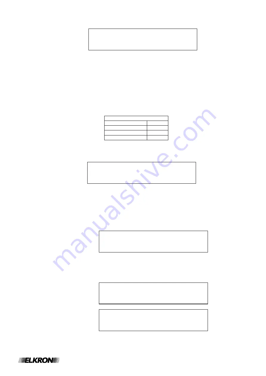
, the following menu is displayed: 


When the menu is entered, the cursor selects the 1

st

 digit of password 1; by using the UP/DOWN keys, the digits 0-9 are scrolled. 

By pressing RIGHT, the cursor moves to the next digit; by pressing LEFT; the cursor moves back to the previous digit. 
After inserting the 4

th

 digit of the generic password, by pressing RIGHT the 1

st

 digit of the next password is selected. 

The cursor always blinks on the currently selected digit. 
 
To quit the menu and discard the entered modifications, press ESC. 
 
By pressing ACK, the passwords are all confirmed at the same time. 
 
Please, note that the passwords 1 and 2 are the level 2 ones, whereas the passwords 3 and 4 are the level 3 ones. 
 
The factory default passwords are reported in the following table: 
 

Factory default passwords 

Password 1 

2222 

Password 2 

2222 

Password 3 

3333 

Password 4 

3333 

3.2.2  System name 

By selecting  

‹‹

SYSTEM NAME


››

 from the programming menu, the following screen is displayed: 


The name currently assigned to the system (

XXXXXXXXXXXXXXX

), with the cursor placed beyond the last character, is shown. 

 
The system name is entered according to the rules described in the section relevant to string input at the beginning of the chapter. 

3.2.3  Zones 

After selecting 

‹‹

ZONES

››

 from the programming menu, the user is required to enter the zone number: 


The  number  to  be  inserted  is  composed  of  2  digits  (the  control  panel  can  handle  up  to  20  zones)  and  it  must  be  entered  by 
following the rules described in the section relevant to number input at the beginning of the chapter. 
 
After entering and confirming the number, if it is valid (i.e., it is relevant to a configured zone) the following menu is shown: 


PASSWORD 
 
1: XXXX    2: XXXX 
3: XXXX    4: XXXX


SYSTEM NAME: 
XXXXXXXXXXXXXXXXXX_


ZONE: __


> NAME 
  MODE 
  RELAY 
  INCLUDE/EXCLUDE 


  VERIFY 


Summary of Contents for C420

Page 1: ...1 24 Installazione MP508 DS80SC86 006A LBT80744 Programming ManualC420 4 20 zones Conventional control panel GB 0051 ...

Page 2: ...al you may find references and information about products hardware or software or services not commercialized yet These references and information do not imply that the company intends to commercialize these products and services Elkron is a trademark of URMET S p A All trademarks mentioned in this document belong to the corresponding owners All rights reserved The total or partial reproduction of...

Page 3: ...N MENU 9 3 1 LANGUAGE 10 3 2 PROGRAMMING 10 3 2 1 Password 10 3 2 2 System name 11 3 2 3 Zones 11 3 2 4 Outputs and Relays 14 3 2 5 Timers 16 3 2 6 Cards initialization 16 3 2 7 Printer 17 3 2 8 LCD annunciator 17 3 3 SERVICE 18 3 3 1 Event log 18 3 3 2 Print Event Log 18 3 3 3 Clock 19 3 3 4 Zone test 19 3 3 5 Batteries test 20 3 3 6 FW revision 20 3 4 EXCLUSIONS 21 3 4 1 Zones 21 3 4 2 Supplemen...

Page 4: ... to the control panel in order to ease the input during the programming phase By using an optional interface card the control panel can be connected to a remote LCD annunciator which shows the contents of the display during the monitoring phase and a printer with Centronics interface for event log printing The control panel is equipped with an event log able to store up to 1000 events Also there i...

Page 5: ...ondition with siren output ON Single knock with delay When the zone is in idle condition and the circuit detects an alarm from one or more points it switches to alarm condition with siren output OFF and an activation timer starts When the timer expires the zone switches to alarm condition with siren output ON Double knock When the zone is in idle condition and the circuit detects an alarm from one...

Page 6: ...GENERAL FAULT YELLOW Steady ON at least one fault is present This indicator provides a cumulative notification of faults Further details on the fault type are provided through the display or dedicated LEDs CPU SYSTEM FAULT YELLOW Steady ON a system fault is present Usually when this LED is turned ON the CPU stops working properly because of an hardware problem e g some peripheral stops working as ...

Page 7: ...enabled the user is required to enter the level 2 password The usage of this key leads to the storage of an event in the event log TEST LAMP This key starts the test lamp procedure which activates the buzzer and turns all the LEDs ON simultaneously for a period of 3 seconds If the key UP is pressed during the execution of the test when it ends the user enters a screen which makes it possible to re...

Page 8: ...P DOWN arrows They perform the same function of the keys LEFT RIGHT UP DOWN available on the internal keyboard see the previous paragraph 2 3 OUTPUTS AND RELAYS The table below describes the outputs and relays available in the control panel OUTPUT RELAY FUNCTION ALARM RELAY This relay is activated when the control panel switches to alarm condition with siren output OFF or ON The relay is deactivat...

Page 9: ...serted By pressing the UP DOWN keys the user selects the digit By pressing RIGHT the inserted digit is confirmed and the cursor selects the next digit The digits already selected and confirmed are replaced by asterisks PASSWORD _ After entering the fourth digit all the passwords have a 4 digits fixed length press RIGHT to confirm the password input If the password is correct the menu functionality...

Page 10: ...enu is entered the selection character selects the currently selected language A different language is selected by using the UP DOWN keys and confirmed by pressing the RIGHT key 3 2 PROGRAMMING The programming menu protected by level 3 password input if the passwords are enabled allows the user to access to the programming options of the control panel When the control panel enters the programming ...

Page 11: ...ory default passwords Password 1 2222 Password 2 2222 Password 3 3333 Password 4 3333 3 2 2 System name By selecting SYSTEM NAME from the programming menu the following screen is displayed The name currently assigned to the system XXXXXXXXXXXXXXX with the cursor placed beyond the last character is shown The system name is entered according to the rules described in the section relevant to string i...

Page 12: ...ITH DELAY HOTEL After having selected the working mode a sequence of screens is shown for the settings of the parameters associated to the chosen mode DELAY This is the delay whose expiration makes the zone in alarm with siren output OFF switch to alarm condition with siren output ON The valid range for this parameter is 1 10 minutes The delay is inserted through the following screen After inserti...

Page 13: ...n during the insertion of parameters the choices entered up to that moment are discarded and the initial screen related to mode selection is displayed again 3 2 3 3 Relay By selecting this item the following menu is shown This menu allows the user to associate a triggering event to the activation of the relay permanently associated to the zone When the menu is entered the selector selects the curr...

Page 14: ...s the currently active option 3 2 4 2 Programmable relay By selecting PROGRAMMABLE RELAY the following menu is shown The programmable relay can be programmed to signal the presence of exclusions or the lack of AC mains The selector position when the menu is entered indicates the current programming option of the relay By selecting NO AC POWER and confirming the selected choice by pressing the RIGH...

Page 15: ...ude the supplementary siren output and confirm the desired option with the RIGHT key By selecting SET the following screen is displayed In this screen it is possible to associate the supplementary siren output to the zones of the control panel Anytime the selector selects one of the zones which can be associated to the siren output By using the UP DOWN keys one of the following characters can be s...

Page 16: ...d in HOTEL mode switches to alarm condition For further details please refer to the section which describes the operating modes of the zones 3 2 6 Cards initialization When this menu item is selected the cards initialization procedure starts This procedure which must be performed upon insertion and removal of cards circuit expansion cards or the supplementary siren outputs expansion card makes the...

Page 17: ... annunciator By selecting this menu item the following menu which allows the user to recognize and configure the LCD annunciator is displayed By selecting ENABLE one of the following messages is shown RECOGNITION ACTIVATED if the LCD annunciator has not been recognized yet EQUIPMENT ALREADY ENABLED if the LCD annunciator has been recognized already By selecting DISABLE one of the following message...

Page 18: ...atest the newest event is displayed In order to return to the previous menu press MENU ESC The inactivity timer associated to this menu is 120 seconds 3 3 2 Print Event Log By selecting this item from the service menu a message is shown This message depends on the state of the printer and the event log printing already ongoing or not EVENT LOG PRINT STARTED if the printer is connected and working ...

Page 19: ... UP DOWN and confirm the choice by pressing RIGHT Press ESC LEFT to discard the selection and return to the service menu 3 3 4 Zone test By selecting this item from the SERVICE menu it is possible to start the test for the functional verification of the zones in alarm When this item is selected and there is no zone test in progress the user is asked to enter the number of the zone to put under tes...

Page 20: ...be started In such a case when the user selects the ZONE TEST item from the SERVICE menu the following message is displayed 3 3 5 Batteries test When this item is selected from the SERVICE menu the batteries test is started on the Command and Control module and the following message is displayed Go back to the previous menu by pressing ESC LEFT 3 3 6 FW revision This menu shows the version and rev...

Page 21: ...o enter the zone number After having entered a valid zone number the zone exclusion menu is shown 3 4 2 Supplementary siren outputs If the supplementary siren outputs expansion card is not present when this menu item is selected the following message is shown Conversely if the expansion card is present the user is asked to enter the number of the supplementary siren output to be included excluded ...

Page 22: ... By entering this menu the user can exclude include the printer 3 4 5 LCD annunciator This menu allows the user to exclude include the LCD annunciator connected to the control panel PRINTER INCLUDED EXCLUDED LCD ANNUNCIATOR INCLUDED EXCLUDED ...

Page 23: ...C420 Programming Manual 23 ...

Page 24: ...LKRON Tel 39 011 3986711 Fax 39 011 3986703 Milano Tel 39 02 334491 Fax 39 02 33449213 www elkron com mail to info elkron it ELKRON is a trademark of URMET S p A Via Bologna 188 C 10154 Torino TO Italy www urmet com Made in ITALY ...

Reviews: