Instructions Printed On Inside
828-397-4200
Voice
828-397-4415 Fax
http://www.elkproducts.com
email: [email protected]
PO Box 100 • Hwy. 70W
•
Hildebran, NC 28637 • USA
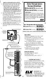
APPLICATION:
Allows the M1 or M1EZ8 to monitor remote tem-
peratures. Rules are used to activate outputs,
dial phone numbers, deliver voice alerts, etc. A
sensor can be interfaced to zones 1-16 of the M1
or zones 1-8 of the M1EZ8. Unit available with
short or long (7 ft.) Probe.
FEATURES:
•
Measures Temperature From: -50 to +140 F
•
Communicates to Control Over 3 Wires
•
Operates On Any Main Board Zone, M1 zones
1-16, M1EZ8 zones 1-8
•
Up to 16 Interfaces May Be Connected To An
M1, Up to 8 Interfaces To An M1EZ8
•
Interface May be Placed Up To 1000 ft Away
•
Suitable for Indoor/Outdoor Use in a Covered
Environment
•
Available with Short Probe (M1ZTS)
or with 7 ft. Probe (ELK-M1ZTSR)
SPECIFICATIONS:
•
Operating Voltage: 12 Volts D.C.
•
Current Draw: 10mA
•
Housing Dimensions: 2.375" x 1.25" x 1"
* * IMPORTANT NOTE * *
For full compatibility with the ELK-M1ZTS or ELK-
M1ZTSR the M1 or M1EZ8 Control must have
firmware version 4.2.5 or higher and the Elk-RP
Software must be version 1.4.1 or higher. Earlier
version firmware/software may appear to work
but will not produce accurate readings.
10/04
Auxiliary
+12VDC Power
Outputs
Master Power Switch (SW1)
,
disconnects AC and Battery
power from control
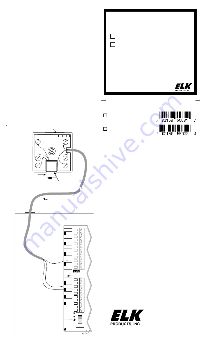
This example shows the
Temperature Interface
connected to Zone 15.
However, any of the 16 main
zones will accept a
Temperature Interface.
Zone Def=033 Temperature
ELK-M1
(Left Side Terminals)
Temperature
Sensor/Interface
with cover
removed
Four conductor cable from
Temperature Inteface to the Control
(Maximum distance: 1000 ft.)
+SAUX
NEG
+VAUX
NEG
+VAUX
NEG
+VAUX
NEG
AC
ZONE 16
NORMAL
JP1
SW1
16.5 V
JUMPER TO
START WITH NO
AC
POWER
TELCO SEIZED
AC
Z9
NEG
Z10
Z11
NEG
Z13
NEG
Z15
Z14
Z12
NEG
Z16
DIALER ACTIVE
2WIRE
SMOKE
STATUS
REVERSE
BAT LEADS
+
-
BATTERY
Red
Green
Black
ELK-M1ZTS "Short"
Temperature Probe
ELK-M1ZTSR "7 ft."
Temperature Probe plugs in here.
+1
2V
ZN
NEG
Red
Green
Black
CAL
+
T
-
Calibration pads - DO NOT USE without
help from ELK Technical Support
INSTALLATION OF M1ZTS or ZTSR
1.
Remove the cover from the base of the Interface.
2.
Mount the base using a #6 x 3/4" sheet metal
screw though hole in center of circuit board.
NOTE: The Interface is not weatherproof. If
mounted outdoors, place under a roof or deck
overhang or in a weather resistant box. For
freezer monitoring or extreme conditions the
model with 7 ft. Probe model (M1ZTSR) is best as it
allows the interface to be mounted away from the
sensor (indoors) in a more suitable environment.
3.
Turn the Control Panel power OFF.
4.
Run a four conductor cable (max. of 1000 ft.) from
the Interface to the Control. Connect the wires
per and diagram steps below:
- Connect a Green wire from terminal ZN on the
interface to any unused Zone input terminal on the
main M1 board (Z1-Z16) or M1EZ8 (Z1-Z8). No
EOL resistor is needed.
- Connect a Red wire from te12V on the
Interface to Aux. +12 Volt DC terminal on control.
- Connect a Black wire from terminal NEG on the
interface to NEG terminal on control.
5.
After all connections are complete, place the
cover on the interface and turn the Control Panel
power ON.
Zone Temperature Sensor/Interface
ELK-M1ZTSR
(7 ft Probe)
ELK-M1ZTS
(Short Probe)
Zone Temperature
Sensor/Interface
ELK-M1ZTS
(Short Probe)
ELK-M1ZTSR
(7 ft. Probe)


