


code: UMS012
review: 0.2
date: 20/04/2022
Laser Welding machine - MS 3.5
user and maintenance manual
page 76 of 102
8.5.4
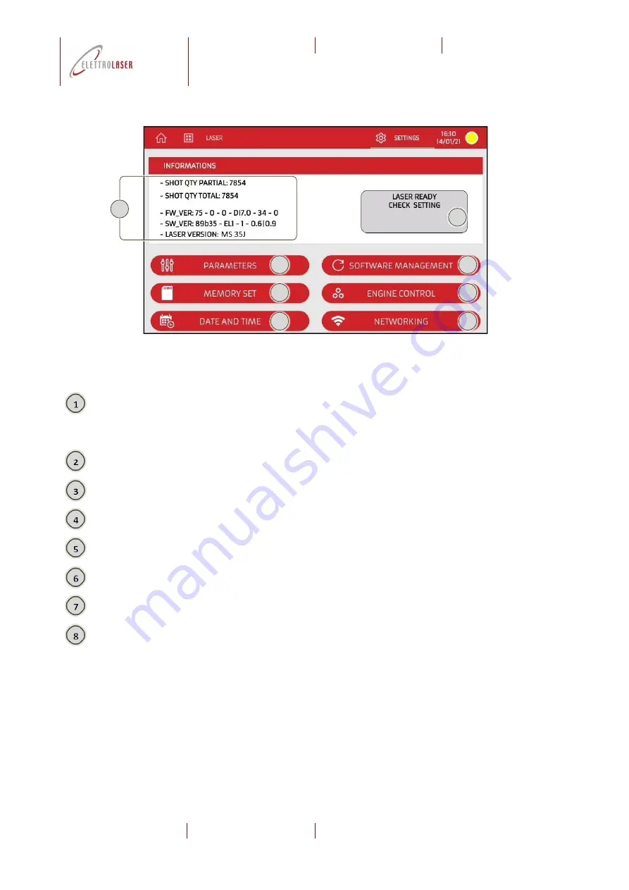
Settings page
Fig. 8-7
–
Settings page
View-only area displaying:
•
The partial number of shots generated by the machine;
•
The total number of total shots generated by the machine;
•
The firmware version number of the machine;
•
The software version number of the machine;
The number of the laser version assembled on the machine.
View-only area displaying the current status of the machine.
When pressed, this control area allows the operator to access the “Parameters” page (paragraph
When pressed, this control area allows the operator to ac
cess the “Memory set” page (paragraph
When pressed, this control area allows the operator to access the date/time settings page (paragraph 8.5.4.4).
When pressed, this control area allows the operator to access the software management page (paragraph 8.5.4.5).
This control area is not available for use.
When pressed, this control area allows the operator to access the network settings page (paragraph 8.5.4.6).
2
3
4
5
6
7
8
1
Summary of Contents for MS 3.5
Page 105: ...code UMS012 review 0 2 date 20 04 2022 Laser Welding machine MS 3 5 annexes...
Page 106: ......
Page 107: ......


