OPERATOR’S
INSTRUCTION MANUAL
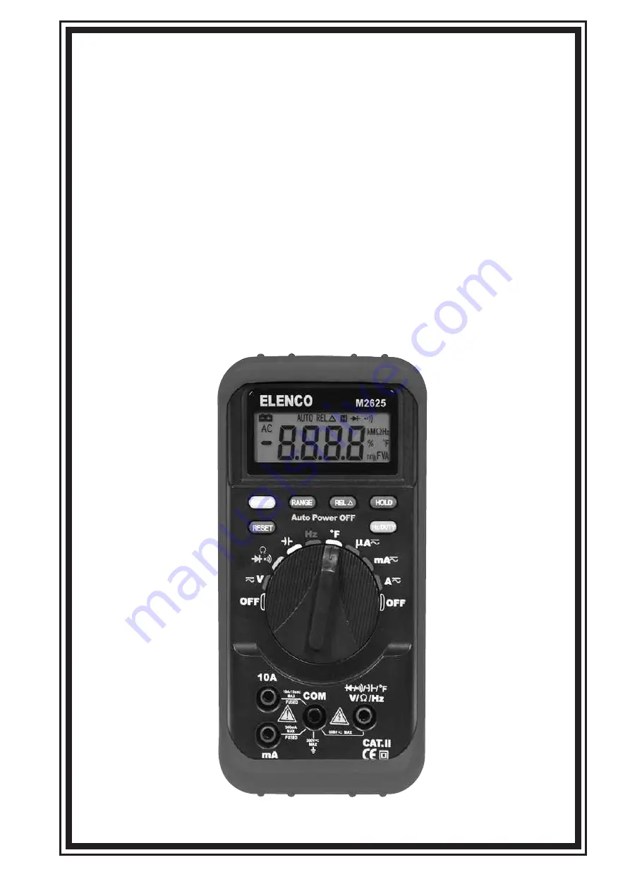
M-2625
AUTO RANGING
DIGITAL MULTIMETER
with Temperature Probe
Copyright © 2007 Elenco
®
Electronics, Inc.
All manuals and user guides at all-guides.com
all-guides.com
Page 1: ...OPERATOR S INSTRUCTION MANUAL M 2625 AUTO RANGING DIGITAL MULTIMETER with Temperature Probe Copyright 2007 Elenco Electronics Inc All manuals and user guides at all guides com a l l g u i d e s c o m...
Page 2: ...Measuring Voltage 12 Measuring DC Voltage 13 Measuring AC Voltage 14 15 Measuring Current 16 Measuring DC Current 17 19 Measuring AC Current 19 21 Measuring Resistance 21 22 Testing Diodes 23 Testing...
Page 3: ...e insulation surrounding the connectors Inspect the test leads for damaged insulation or exposed metal Check the test leads for continuity Replace damaged test leads before you use the meter The RESPO...
Page 4: ...to possible electric shock or personal injury replace the batteries as soon as the low battery indicator appears Use only type AA batteries or equivalent properly installed in the meter case to power...
Page 5: ...late of Meter Figure 1 Front plate of the meter 5 AC Alternating Current Important Information DC and AC Caution risk of electric shock DC Direct Current Earth Ground Equipment Safety Standard Low Bat...
Page 6: ...le 4 and Figure 3 6 Terminal Function Description OF V Hz Volts ohm diode frequency DUTY temperature and capacitance measurement and testing for continuity terminal mA Milliampere current microampere...
Page 7: ...ary Switch Symbols 7 Position of Switch Function V DC AC voltage measurement Resistance measurement diode test testing for continuity Capacitance measurement Hz Frequency measurement Duty cycle measur...
Page 8: ...the auto range mode press the RANGE button to select the desired measurement range manually The range goes from minimum to maximum by pressing the RANGE button multiple times and returns to minimum a...
Page 9: ...ons 4 HOLD data hold Pressing the HOLD button enables the data hold function and an H symbol appears on the display The momentary value appears on the display Press the HOLD button again to exit this...
Page 10: ...nt indicator 4 Battery power is weakening 5 RS232 Serial transmission not used on this meter 6 Auto Auto range indicator 7 REL Relative measurement 8 Data hold 9 Diode symbol 10 Audible continuity fun...
Page 11: ...the meter have more than one range 1 It is important to select the correct range If the range is too small OL shows on the display for overload If the range is too large the value of the reading will...
Page 12: ...any position away from the OFF position The battery voltage is adequate when the indication is clear and the symbol is not on the display If the symbol appears on the display or nothing shows on the d...
Page 13: ...h to the V position then AUTO and mV symbols are indicated on the display 4 Connect the black test lead to the negative side of the circuit under test and the red test lead to the positive side of the...
Page 14: ...n AUTO AC and V symbols are indicated on the display 4 Connect the test leads to the circuit under test then the measured value is indicated on the display 5 When measuring voltage less than 400mV pre...
Page 15: ...an 20mV at the 400mV AC range the measurement value cannot be indicated correctly Even if shorted the input line at the 4V AC range 1 3 digits may remain indicated In that case by pressing the REL but...
Page 16: ...t when the leads are plugged into the current terminals Maximum measurement time allowed at the 10A current range function is 15 seconds If you carry on making a measurement continuously over 15 secon...
Page 17: ...cuit under test and the red test lead to the positive side of the circuit so the meter is in series with the circuit 5 Turn the on the power for the circuit under test 6 The measured value is indicate...
Page 18: ...Figure 8 DC Current Measurement 18 All manuals and user guides at all guides com...
Page 19: ...COM terminal and the red lead in an input appropriate for the measurement range as shown in Table 6 4 Connect the test leads to the circuit under test so the meter is in series with the circuit 5 Set...
Page 20: ...Note To avoid blowing the meter s 500mA fuse use the mA terminal only if you are sure the current is less than 400mA Figure 9 AC Current Measurement 20 All manuals and user guides at all guides com...
Page 21: ...r test disconnect the circuit power and discharge all high voltage capacitors before measuring resistance Resistance is an opposition to current flow The unit of resistance is the ohm The meter measur...
Page 22: ...shown on the display Keep the following in mind when measuring resistance Because the meter s test current flows through all possible paths between the probe tips the measured value of a resistor in...
Page 23: ...devices The test sends a current through a semiconductor junction then measures the junction s voltage drop A typical junction drops 0 5V to 0 8V To test a diode out of a circuit set up the meter as...
Page 24: ...of a complete path for current flow The continuity test features a beeper that sounds if a circuit is complete the resistance less than 120 approx The beeper allows you to perform quick continuity tes...
Page 25: ...d of time according to the measuring capacitance Measuring capacitance 4 F Measuring time is about 2 seconds Measuring capacitance 40 F Measuring time is about 7 seconds Measuring capacitance 100 F Me...
Page 26: ...Figure 13 Capacitance Measurement 26 All manuals and user guides at all guides com a l l g u i d e s c o m...
Page 27: ...urn on the meter then set up the meter as shown in Figure 14 2 Insert the black test lead into the COM terminal and the red test lead into the terminal 3 Set the Function Rotary Switch to the Hz posit...
Page 28: ...n in Figure 15 2 Insert the black test lead into the COM terminal and the red test lead into the terminal 3 Set the Function Rotary Switch to the Hz position Then press Hz DUTY once to select DUTY Cyc...
Page 29: ...eter as shown in Figure 17 2 Set the Function Rotary Switch to the OF position then the AUTO and OF symbols are indicated on the display 3 Plug the positive leg of the type K thermocouples into the te...
Page 30: ...Figure 17 Temperature Measurement 30 All manuals and user guides at all guides com...
Page 31: ...es R6P or equivalent Warning To avoid false readings which could lead to possible electric shock or personal injury replace the batteries as soon as the low battery indicator appears Replace the batte...
Page 32: ...eter Then using a screwdriver unscrew the two screws on the back case and remove it 3 Remove either fuse by gently prying one end loose then sliding the fuse out of its bracket 4 Install ONLY the spec...
Page 33: ...II double insulation Operating Environment Temperature 32O 104OF 0O to 40OC humidity 80 RH Storage Environment Temperature 4O 140OF 20O to 60OC humidity 85 RH Power Two 1 5V AA batteries Dimensions 6...
Page 34: ...n Accuracy Note 40 A 0 1 A 2 0 rdg 5 Overload Protect Fast fuse 0 5A 250V and fast fuse 10A 250V 10A for 15sec maximum Input Voltage Drop 0 4V 400 A 1 A 40mA 10 A 1 5 rdg 5 400mA 100 A 4A 1mA 2 0 rdg...
Page 35: ...tect 250V rms 400nF 100pF 3 0 rdg 5 4 F 1nF 40 F 10nF 100 F 100nF 3 5 rdg 5 Range Description Note Display reads approximate forward voltage of diode Forward DC current approx 1 5mA Reversed DC voltag...
Page 36: ...Elenco Electronics Inc 150 Carpenter Avenue Wheeling IL 60090 847 541 3800 Web site www elenco com e mail elenco elenco com All manuals and user guides at all guides com a l l g u i d e s c o m...