69
Operating Guide
PSI 8000 3U HS PV Series
EN
Date: 20-05-2016
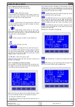
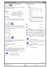
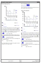
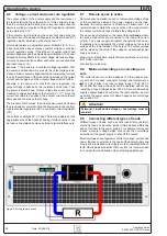
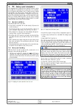
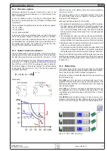
Figure 12. Adjustment of maximum power
2. Switch the output on. Power is then not adjustable anymore.
3. The DC output will be set to a calculated idle voltage (read
below)
4. Switch the DC-AC inverter on.
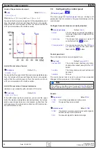
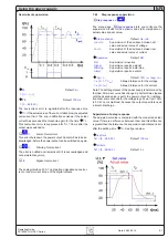
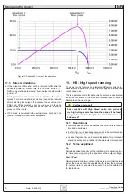
The power supply will then turn the adjusted initial values into
the power characteristics curve of the simulated solar panel. The
curve in the figure below depicts an example with initial current
= 8 A and initial power (MPP) = 8 kW. The U
MPP
and U
Idle
result
automatically according to the U-I characteristics.
Note
Together with this operating guide you should have received
a CD that contains calculation tools in form of Microsoft Excel
sheets, one for each PV model. Those sheets are used to
enter the same initial values for the simulated solar panel and
to generate and display the resulting characteristics curve.
You can now run a test with the inverter. In order to simulate
different illumination situations, you can
5. Adjust the current set value of the power supply.
When the output is switched off again, power and current are
rest to the initial testing values.
Attention!
The DC output voltage (or simulated solar panel voltage)
is depending on the settings of power and current. Wrong
values may result in an output voltage higher than the
DC-AC inverter can take. In order to protect the inverter,
you are advised to always set the overvoltage protection
threshold (OVP) to the maximum inverter input voltage.
See section 7.6.1, item
Uovp
.
11. PV - Solar panel simulation
The integrated photovoltaics feature enables the power supply
to simulate the characteristics of a solar panel. It‘s a combina-
tion of hardware and software. The PV feature can be enabled
and disabled in the device setup, as described in section „7.8.
Activating the photovoltaics feature“. If disabled, the power sup-
ply acts like a standard power supply unit. If enabled, the power
set value is directly effected by the current set value, resulting
in a voltage-current-power behaviour that is related to a certain
characteristics curve similar to solar panels.
11.1 Special conditions
Following applies for PV operation:
•
If the output is switched off, the start values of power and
current can be set
•
The power set value can not be changed if the output is on
and is calculated depending on the set value of current
•
If the output is on, the power set value display changes ac-
cording to the current set value adjustment
•
Remote control of PV operation via digital or analog interface
is possible the same way as with manual control on the front
panel
•
When switching the output off again the start values, which
have been set before the output was switched on the last
time, are restored
•
The calculated power, which depends on the current set value,
is clipped to the maximum power of the device
11.2 Setup and handling
With the DC-AC inverter connected, the procedure to run a
simulation of a solar panel is like this:
1. With the power supply DC output switched off and PV feature
activated, you need to adjust initial power and initial current
set values, which characterise the solar panel that is going
to be simulated.
Figure 11. Adjusting the solar panel short-circuit current
Operating the device

