Next Generation Solar Powered LED Matrix Lighting
1 -LED Matrix Light Unit 1- Li-Polymer Rechargeable Battery (EE-LPB-1.0AH) 1 - Solar Panel (EE-SOP-3.0W)
1 -Wall Mount Plate w/hardware 1–AC-DC Power Adapter (EE-DCP-1.0A, Bonus) 1 -Table Stand (Bonus)
Thank you for purchasing the
LED Matrix Light. With its effortless setup and lightweight design, the
LED
Matrix Light conforms to all your lighting needs. It was made to provide many years of service using environmentally friendly
solar power. North America patented invention and technology, other patents pending worldwide, all rights reserved.
This document guides you through the following:
EE836DE
User Manual
Installation
(
see
Fig.1
)
Introduction and Intellectual property Rights Statement
What’s Inside the Package
● What’s Inside the Package ● Installation ● Functions ● User Tips
● Specifications ● Optional Accessories ● Important Safety Information ● Limited Warranty information
Functions
Refer to the 3-position switch and 2 adjustable knobs on the bottom of the light (see Fig. 2) :
Rev. EE836DE M042010EV Page 1
position: No illumination. (EMG still functions, see Fig 3. on back page)
position: Unit illuminates in dark with motion detection based on adjustments for
DELAY TIME & SENSITIVITY/RANGE during initial set up/Walk test period.
indicator (Red LED inside the motion head) flashes to indicate motion during 10
minutes extendable Initial set up/Walk test period or for low battery status.
position: Integrated “Smart On” feature enables the unit to illuminate continuously under
low ambient light conditions with
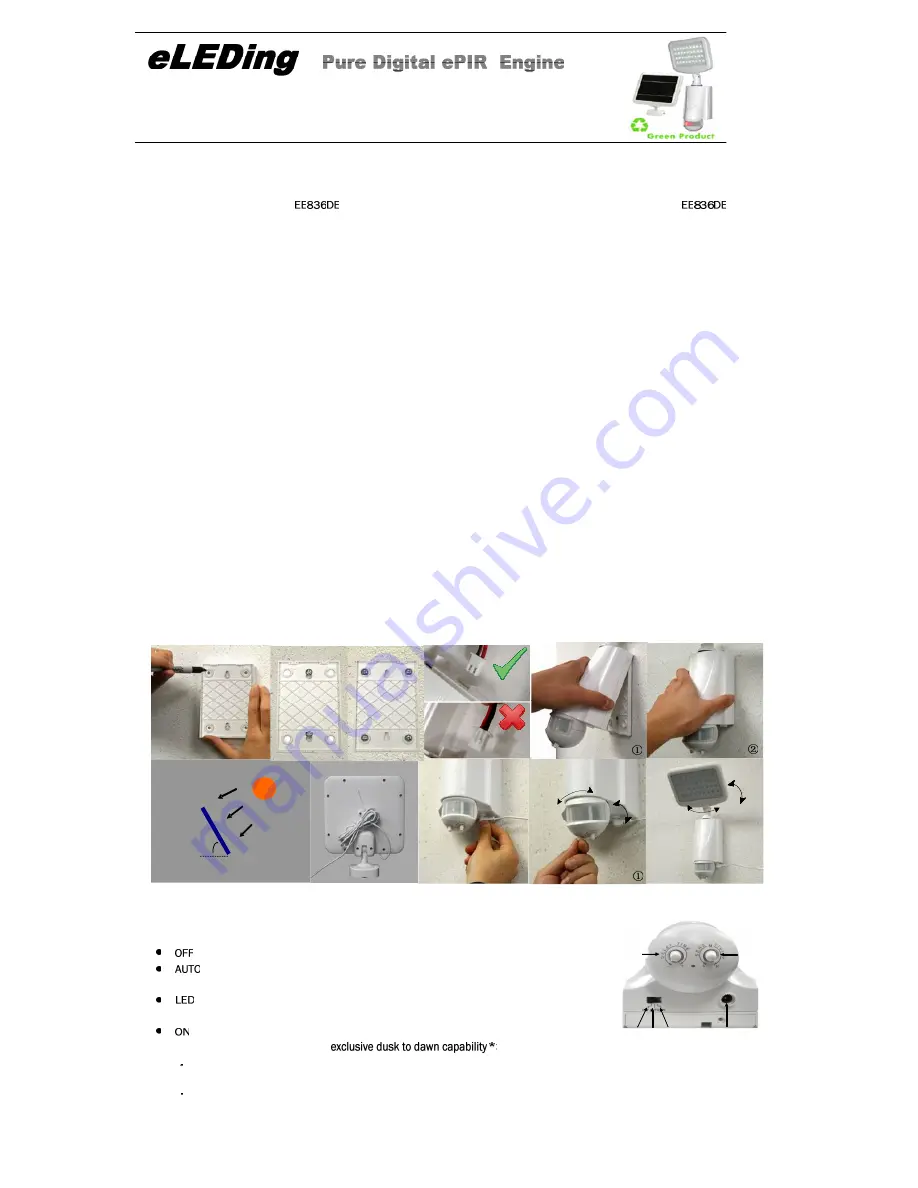
7. Plug the solar panel into the bottom of the light. Before initial operation, it is suggested to charge the light for at least 2 hours using
the included AC-DC adapter, or using solar panel to charge it for 2-3 days.
8. Switch to AUTO position to start Initial set up/Walk test procedure. Please refer to “Testing Method” at Page 2 for procedure details.
1. Choose a flat and stable surface, mark back mount base two standard holes ( 2 or 4 holes) on the surface.
For concrete/brick/stucco: Predrill into marked locations suggesting with a 3/16" drill bit. Insert plastic anchors and apply screws.
Attach wall mount.
4. Attach the unit with wall mount plate:
①
First connect top part of wall mount plate with the light body as a “hinge",
②
T
hen push the light toward wall plate to snap-in.
2. For wood surfaces: Drill the screws into the pre-marked locations and attach wall mount.
5. Place the solar panel in the most sunny location where maximum sunlight can be collected, use screws provided to mount on the wall,
roof, or patio, etc. Refer to Fig 1(5) Solar panel position.
9. After Initial set up/Walk test, keep the switch at AUTO position, if there is no motion during the delay time, the unit will enter into
normal operation and illuminate only when it is dark.
6. Tie the solar panel extra power wire using zip-tie and hide it behind the panel.
①
Adjust the direction of motion detector, delay time, sensitivity/range
②
Fig. 1. Installation Steps
Please Read Before Install the Unit!
Fig. 2.
Light bottom
Adjust the light head (LED matrix) direction.
®
Sensitivity
OFF AUTO ON
Delay time
Solar/DC power Input
Fig. 2. Functions
A Lowering brightness to a reasonable level during quite period /no movement
B. Illuminating at maximum brightness once motion is detected
C Preventing battery damage from over discharging (<10% battery capacity /critical emergency ): Once voltage falls below
T
P
8.
7.
1.
Sun
35 - 80
o
o
3. Open battery cover on the back of the unit, and insert the battery plug into main unit. Observing connector direction refer to Fig 1(3).
Close battery cover.
4.
4.
T
p
6.
7.
8.
②
5.
Pan & Tilt
3.
Yes
No
®
(Demo Video: www.eLEDingStore.com/EE836DE)
OR
2.
Solar Panel Position


