SERVICE MANUAL
© Electrolux
Muggenhofer Straße 135D-90429 NürnbergGermany
Fax +49 (0)911 323 1022
Spares Operation
Publ.-Nr.:599 51 13 34685
02.02
EN
Edition:
Dishwasher
GS 23 CHGS 24 CH
DISHWASHER
Page 1: ...SERVICE MANUAL Electrolux Muggenhofer Straße 135 D 90429 Nürnberg Germany Fax 49 0 911 323 1022 Spares Operation Publ Nr 599 51 13 34 685 02 02 EN Edition Dishwasher GS 23 CH GS 24 CH DISHWASHER ...
Page 2: ...er Pretest 22 4 9 Computer Pretest sequence 23 4 10 Alle Waschprogramme 24 4 10 1 Gläserprogramm 24 4 10 2 Normal programme 25 4 10 3 Intensive programme 26 4 10 4 Short programme 27 4 10 5 Pre rinse 28 5 Functional description of GS 24 electronic system s 29 5 1 Overview of the electronics used in this series 29 5 2 Mechanical structure 30 5 3 Comparison with front panels of generation GS 23 31 5...
Page 3: ...ir instructions 49 10 Handling of complaints 58 11 Service Instructions 61 11 1 Installation instructions for door sealing for dishwashers PNC 153 02 37 02 1 61 11 2 Spacers on support panel and on electronic 62 11 3 Top basket spray arm right handed 64 ...
Page 4: ...elated and or VDE 0700 ICE 65 appliance related Components are in accordance with IEC and or VDE directives For replacements use parts of the same specification only With control systems provided with MOS modules use parts of the same specification only Observe all MOS regulations when handling MOS components Only carry out mechanical repairs or checks of mechanical components when these are dead ...
Page 5: ...The inlet hose consists of high quality plastic with approved compressive and buckling resistance A sieve is incorporated on the connection side to eliminate contamination from the supply network as well as a rubber seal When making the connection take care that sieve and seal are in their correct positions After opening the shut off control no water is allowed to leak from the threaded joint With...
Page 6: ... hoses to prevent these from being squeezed or buckled Align the dishwasher to centreline of the niche and flush with the side ledges by fitting in adjustment plates if necessary Carefully open appliance door to avoid changing the adjusted appliance Fix appliance with screws through provided holes to the sidewalls of the piece of furniture on both sides in upper inner area see Detail A Before secu...
Page 7: ...ose lying to niche base Edge close lying to body side wall according to Detail A Press on and fix in its position the side ledge SL L secure with the supplied screws 2 off SCHR Repeat the procedure with side ledge SL R Thickness of body side wall 16 mm Remove protective strip of the 2 spacer washers DS 1 mounted to the side ledges SL R SL L Adhere the spacer washers 3 mm DS 2 supplied loosely acco...
Page 8: ...ce to both cold and hot water max 65 C Water pressure 1 to 10 bars flow pressure A regulating tap of outgoing connection G should be provided by the Customer The inlet hose is a plastic compression hose with sieve SVGW approved 25 bars It is recommended to install an IRG filter Drainage Install the flexible drainage hose of an inner diameter of 22 mm without buckles The drainage of the appliance i...
Page 9: ...al accessories available Additional lugs at the cover PNC 153 04 02 00 Detail D Detail C Detail B Detail D Circuit Radiator voltage 230 V Electrical connection A licensed electrical fitter should install the connection to the mains The appliance is provided with a power cable 3 x 1 mm2 with injection moulded plug type 13 You should connect the dishwasher to the mains by means of a plug or an all p...
Page 10: ...ry type control knob A Drain G Appliance dimensions K Cold water connection N Niche dimensions W Hot water connection E Socket Water installation Inlet You may connect the appliance to both cold and hot water max 65 C Water pressure 1 to 10 bars flow pressure A regulating tap of outgoing connection G should be provided by the Customer The inlet hose is a plastic compression hose with sieve SVGW ap...
Page 11: ...board Push the appliance in while continuously drawing along the cables and hoses ensuring to prevent these from being buckled Align the dishwasher and secure it at both sides in the upper part of the washing compartment shell Detail B Optional fitting positions At the base Detail C Optional accessories available Additional lugs at the cover PNC 153 04 02 00 Detail D ...
Page 12: ...h of a minimum of 3mm contact distance should be provided within the fixed installation for isolation from the mains Installation on the part of the customer Install fuse feeder and socket according to the wiring schematic Connect plug supplied by Customer according to instruction label on power cable Switching over to 230 V 6 A 15 kW Should be carried out by a licensed electrical fitter Isolate a...
Page 13: ...cium stains will be left behind on the crockery and cutlery Consult your competent waterworks for information about the water hardness and hardness range within your residential area With a water hardness below 5 dH there is no need for filling any regenerating salt In this incident the salt display is constantly lit Set the amount of dosage as follows Turn the dosing knob by means of a coin or sc...
Page 14: ...ence indicator available 4 programmes normal intensive short pre rinse 1 additional function Eco 2 incorporated Pretests Comfort levels GL 1 Gli 1 GSB 2 GSIB 2 5 Key Electronic PNC 153 0259 05 8 Internal designation TES 401 153 0842 00 2 red LEDs salt and shine agent 5 green LEDs for all programmes Eco and Half load 5 yellow LEDs as programme sequence indicator 4 programmes normal intensive short ...
Page 15: ...rammes glasses normal intensive short pre rinse 3 additional functions Eco half load start delay 2 incorporated Pretests Comfort levels Fust GS 912 7 Key Electronic PNC 153 0259 07 4 Internal designation TES 407 153 0891 00 2 red LEDs salt and shine agent 7 green LEDs for all programmes Eco and Stop 5 yellow LEDs as programme sequence indicator 1 7 segment display for start delay 4 programmes norm...
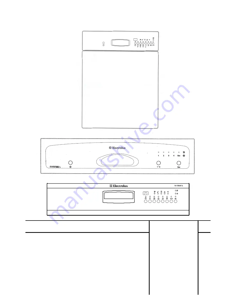
Page 16: ...67 00 3 Comfort levels GL Gli GSB 1 GSIB 1 6 Key Electronic ET 153 0259 02 5 Comfort levels SL Sli GSG 1 GSIG 1 8 Key Electronic ET 153 0259 01 7 Comfort levels Fust GS 912 7 Key Electronic ET 153 0259 03 3 1 Normal 2 Intensive 3 Short 4 Pre rinse 1 Normal 2 Intensive 3 Short 4 Pre rinse 5 Eco 1 Glasses 2 Normal 3 Intensive 4 Short 5 Pre rinse 6 Eco ...
Page 17: ...rection from average value is always at the end of a heating cycle 2 and 5 key Electronics Completely new electronics Snap on case Single board solution in SMD technology Fibre optic between LED display and top of case snapped into the case from the front Mechanical ram incorporated in the case cover for transmission of input commands from rubber keypad to the pushbuttons High resistance signal in...
Page 18: ...lts are on display Comfort levels GL 1 Gli 1 GSB 2 GSIB 2 5 Key Electronic PNC 153 0259 05 8 The yellow END LED together with one of the green programme LEDs among the listed ones are flashing A total of 5 faults are on display Comfort levels SL 1 Sli 1 GSG 2 GSIG 2 Comfort levels Fust GS 912 8 Key Electronic PNC 153 0259 06 6 7 Key Electronic PNC 153 0259 07 4 A letter is displayed on the screen ...
Page 19: ...en R ckschaltniveau nicht erreicht Ablaufpumpe defekt Grobsieb verschmutzt Ablaufschlauch geknickt verstopft Druckw chter defekt X X E Maximale Nachf llzeit von 45 sec oder maximal erlaubte Anzahl von 3 Nachf llen berschritten Zulaufschlauch l t zu wenig Wasser durch Siebe verstopft Wasserdruck zu niedrig Verkalkungen im gesamten Wasserzulauf Maschine verliert Wasser Druckw chter Druckw chterschla...
Page 20: ...nding LEDs are permanently lit The programme starts to run Key Stop Only 8 key PNC 153 0259 06 6 and 7 key PNC 153 0259 07 4 If you stop the programme by using the stop key the green LED Stop and Eco will flash Now you have to switch OFF and ON again the control system or else no input is possible Attention There is water in the machine If you start the pretest again as described under Start the w...
Page 21: ...p Heater level 1 Dispenser Regeneration Action 1 3 sec Check if all LED s are working 2 75 sec Fixed filling time of 75 sec 3 open When level 1 is switched on heating until water temp has reached 60 C otherwise main pump on only for 5 sec without heater 4 20 sec Paused LED flashing 5 45 sec Fixed draining DW is going to be emptied ...
Page 22: ... and or the corresponding LEDs are permanently lit The programme starts to run Key Stop Only 8 key PNC 153 0259 06 6 and 7 key PNC 153 0259 07 4 If you stop the programme by using the stop key the green LED Stop and Short will flash Now you have to switch OFF and ON again the control system or elese no input is possible Attention There is water in the machine If you start the pretest again as desc...
Page 23: ...therwise paused for 5 sec 3 60 sec Fixed filling 60 sec 4 20 sec Check of sprayarm turning speed and dispenser 5 5 sec Check of regeneration valve 6 5 sec Check of mains pump and heater if level 1 is switched on 7 90 sec Overfilling with max 90 sec 8 Automatic operating Drain pump engaged if NIV 2 reached external power off push buttons remain pressed or Hand operating Jumps directly from step 7 t...
Page 24: ...VL 27 22 52 33 47 26 47 26 P R M 23 30 20 30 19 30 17 P R 24 5 20 5 19 5 17 P R 25 25 20 25 19 25 17 P R 26 62 19 57 18 57 16 P R M 27 120 13 120 13 120 13 M 28 P0 11 P0 11 P0 11 29 10 11 10 11 10 11 30 600 10 600 10 600 10 M 31 10 1 10 1 10 1 Legend P1 Fixed filling time of max 15 sec or until NIV1 is switched on CP0 Fixed draining time of max 20 sec then test if NIV1 is switched off P0 Draining ...
Page 25: ... 5 38 5 19 P PA R 25 25 20 25 38 25 19 P PA R 26 65 19 65 37 62 18 P PA R M 27 120 13 120 13 M 28 P0 11 P0 31 P0 11 29 10 11 10 31 10 11 30 600 10 1800 30 600 10 M 31 10 1 10 1 10 1 Legend P1 Fixed filling time of max 15 sec or until NIV1 is switched on CP0 Fixed draining time of max 20 sec then test if NIV1 is switched off P0 Draining by pump until NIV1 is switched off VL Fixed filling time of 60...
Page 26: ...P0 35 P0 33 P0 29 20 10 35 10 33 10 29 CP0 21 VL 34 VL 32 VL 28 22 60 32 55 30 55 27 P R M 23 30 21 30 20 30 19 P R 24 5 21 5 20 5 19 P R 25 25 21 25 20 25 19 P R 26 70 20 65 19 65 18 P R M 27 120 13 120 13 120 13 M 28 P0 11 P0 11 P0 11 29 10 11 10 11 10 11 30 600 10 600 10 600 10 M 31 10 1 10 1 10 1 Legend P1 Fixed filling time of max 15 sec or until NIV1 is switched on CP0 Fixed draining time of...
Page 27: ... 22 57 24 52 20 52 20 P R M 23 30 9 30 9 30 9 P R 24 5 9 5 9 5 9 P R 25 25 9 25 9 25 9 P R 26 62 8 57 8 57 8 P R M 27 120 5 120 5 120 5 M 28 P0 3 P0 3 P0 3 29 10 3 10 3 10 3 30 120 2 120 2 120 2 M 31 10 1 10 1 10 1 Legend P1 Fixed filling time of max 15 sec or until NIV1 is switched on CP0 Fixed draining time of max 20 sec then test if NIV1 is switched off P0 Draining by pump until NIV1 is switche...
Page 28: ...5 4 180 4 R M 5 6 7 P0 1 8 10 1 CP0 9 10 11 12 13 14 15 16 17 18 19 20 21 22 23 24 25 26 27 28 29 30 31 Legend CP0 Fixed filling time of max 20 sec or until NIV1 is switched on P0 Draining by pump until NIV1 is switched off VL Fixed filling time of 60 sec R Refill function active max 3 times for 15 sec each M Minute wise back counting of remaining washing time ...
Page 29: ...C 153 0259 05 8 Internal designation TES 401 153 0842 00 2 red LEDs salt and shine agent 6 green LEDs for all programmes Eco and half load 5 yellow LEDs as programme sequence indicator 4 programmes normal intensive short pre rinse 2 additional functions Eco and half load 2 incorporated Pretests 5 Functional description of GS 24 electronic system s 5 1 Overview of the electronics used in this serie...
Page 30: ...to prevent the same programmes under series GS 23 and series GS 24 from being provided with different indexes 5 2 Mechanical structure Lowest comfort level Support panel made of plastic design panel in varnished steel or stainless steel The design panel will be interlaced with the support panel Medium comfort level Support panel made of plastic design panel from glass decorating strips of varnishe...
Page 31: ...SIA 2 2 key Electronic PNC 153 0259 04 1 1 Normal 2 Intensive 3 Short 4 Pre rinse 1 Normal 2 Intensive 3 Short 4 Pre rinse 5 Eco 1 Glasses 2 Normal 3 Intensive 4 Short 5 Pre rinse 6 Eco Comfort levels GL 1 Gli 1 GSB 2 GSIB 2 5 key Electronic PNC 153 0259 05 8 Comfort levels SL 1 Sli 1 GSG 2 GSIG 2 8 key Electronic PNC 153 0259 06 6 ...
Page 32: ...red by VDR All consumers Triac controlled Pump capacity limited to 120VA by fixed phase angle half load and AAA Temperature range from 0 to 60 C Humidity range from 35 to 85 rel 5 4 Structure technical and new functions Sensor Field Function With the 8 sensor electronic a second electronic system glued on to the glass back is assigned with the function of the mechanical keys Each sensor field gene...
Page 33: ...among the listed ones are flashing A total of 5 faults are on display Comfort levels SL 3 Sli 3 8 Key Electronic PNC 153 0259 09 0 A letter is displayed on the screen and the yellow END LED together with one of the green programme LEDs among the listed ones are flashing A total of 6 faults are on display Code A and or END LED and or Normal are flashing Maximum filling timme of 105 sec exceeded bef...
Page 34: ...ts the heating circuit too early or in irregular manner Code L and or END LED and or Eco are flashing Short circuit or interruption at NTC temperature sensor Possible causes NTC sensor damaged wiring of NTC sensor damaged Code E2 only displayed on 8 key electronic for 2 seconds after activation of main switch The appliance loses stored values in case of mains failure or when activating the main sw...
Page 35: ...the corresponding LEDs are permanently lit The programme starts to run Stop main switch If you stop the programme by means of the main switch you can immediately select a wash programme when switching ON again If you start the pretest again as described under Start the programme jumps directly to Step 5 first pumping the water off the trough corresponding LEDs flashing at the end Now you can resta...
Page 36: ...sive 8 keys PNC 153 0259 09 0 Half load and Short together Switch ON main switch Hold the key s pressed for at least 5 sec corresponding LEDs are flashing during this time The display shows the upper circle of the number 8 and or the corresponding LEDs are permanently lit The programme starts to run Stop main switch If you stop the programme by means of the main switch you can immediately select a...
Page 37: ...r 5 sec 3 60 sec Fixed filling 60 sec 4 20 sec Check of sprayarm turning speed and dispenser 5 5 sec Check of regeneration valve 6 5 sec Check of mains pump and heater if level 1 is switched on 7 90 sec Overfilling with max 90 sec 8 Automatic operating Drain pump engaged if NIV 2 reached external power off push buttons remain pressed or Hand operating Jumps directly from step 7 to step 9 9 50 sec ...
Page 38: ...8 43 P C M or or or 11 55 9 45 7 43 14 240 44 240 36 240 36 P M 15 P0 40 P0 32 P0 32 16 10 40 10 32 10 32 CP0 17 VL 39 VL 31 VL 31 18 120 37 120 30 120 30 P R M 19 P0 35 P0 28 P0 28 20 10 35 10 28 10 28 CP0 21 VL 34 VL 27 VL 27 22 52 33 47 26 47 26 P R M 23 30 20 30 19 30 17 P R 24 5 20 5 19 5 17 P R 25 25 20 25 19 25 17 P R 26 62 19 57 18 57 16 P R M 27 120 13 120 13 120 13 M 28 P0 11 P0 11 P0 11...
Page 39: ... 2 0 11 5 61 5 2 0 5 56 ARD 12 60 61 60 1 5 60 56 P R 13 47 60 t 45 1 5 47 55 P C M or or 12 60 t 47 2 4 11 55 14 600 48 T t 1 4 600 44 P M 15 P0 38 P0 56 P0 34 16 10 38 10 56 10 34 CP0 17 VL 37 VLA 55 VL 33 18 180 36 300 54 180 32 P PA R M 19 P0 34 P0 49 P0 29 20 10 34 10 49 10 29 CP0 21 VL 33 VL 48 VL 28 22 57 32 52 47 52 27 P PA R M 23 30 20 30 38 30 19 P PA R 24 5 20 5 38 5 19 P PA R 25 25 20 ...
Page 40: ... 120 69 120 64 P M P0 72 P0 67 P0 62 10 72 10 67 10 62 CP0 VL 71 VL 66 VL 61 5 71 5 66 5 61 ARD 60 69 60 65 60 60 P R 65 68 60 64 60 59 P C M or or or 15 68 13 61 12 59 780 53 780 51 780 47 P M P0 40 P0 38 P0 34 10 40 10 38 10 34 CP0 VL 39 VL 37 VL 33 180 37 180 35 180 32 P R M P0 35 P0 33 P0 29 10 35 10 33 10 29 CP0 VL 34 VL 32 VL 28 60 32 55 30 55 27 P R M 30 21 30 20 30 19 P R 5 21 5 20 5 19 P ...
Page 41: ...36 5 33 ARD 12 60 42 60 36 60 33 P R 13 43 41 38 35 38 32 P C M or or or 9 39 7 33 6 30 14 120 31 120 27 120 25 P M 15 P0 29 P0 25 P0 23 16 10 29 10 25 10 23 CP0 17 VL 28 VL 24 VL 23 18 60 27 60 23 60 22 P R 19 P0 26 P0 22 P0 21 20 10 26 10 22 10 21 CP0 21 VL 25 VL 21 VL 21 22 57 24 52 20 52 20 P R M 23 30 9 30 9 30 9 P R 24 5 9 5 9 5 9 P R 25 25 9 25 9 25 9 P R 26 62 8 57 8 57 8 P R M 27 120 5 12...
Page 42: ... 51 13 34 EN 5 8 5 Pre rinse Ver F STEP FILLING DRAINING WASHING HEATING KDG REGENERATION DRYING PRE RINSE DISPLAY REMARKS 1 2 3 VL 5 4 180 4 R M 5 6 7 P0 1 8 10 1 CP0 9 10 11 12 13 14 15 16 17 18 19 20 21 22 23 24 25 26 27 28 29 30 31 ...
Page 43: ...0 sec VLB Fixed filling time of 58 sec VLA Fixed filling time of 55 sec VLX Fixed filling time of 52 sec VL Fixed filling time of 50 sec ARD Disabling multiple control pulses KDG Antirepeat Dispenser P Reduction of pump capacity to 120 VA half load R Refill function active max 3 times for 15 sec each C Test of NIV1 before heating is switched on M Minute wise back counting of remaining washing time...
Page 44: ... 44 Spares Operation 07 02 A B 599 51 13 34 EN 6 Wiring Diagrams 6 1 Example GS 23 feeder cable ...
Page 45: ... 45 Spares Operation 07 02 A B 599 51 13 34 EN one unit Example GS 23 Feeder cable 3 x 1 mm 2 with injection moulded plug ...
Page 46: ...osing unit KON Condenser LP Lye pump NIV Level switch RKG Reed contact shine agent RKs Reed contact salt RV Regenerating valve SI Fuse 1AT RC F RC filter TB1 Safety fuse 229 C TB8 Temperature limiter 80 C NTC Thermal sensor NTC TK Door contact TS Touch Sensor Print UES Overflow protection UP Recycling pump black brown blue red white black blue red white black blue red white WIRING SCHEMATIC Type G...
Page 47: ...V Water plus switch NIV Pressostat PGS Programme sequential circuit RG REED relay rinsing agent RUG RKG RS REED relay salt RKS RV Regeneration valve RC F Antiparasitic capacitor TB1 Safety fuse 206 229 C TB1 Safety thermostat 95 C TB8 Safety thermostat 80 C T5 Thermostat 48 C T6 Thermostat 58 C TK Door switch TM PGS motor UES Overflow protection switch UP Recycling pump NTC NTC sensor HR Relay SI ...
Page 48: ...g compartment Spray arm Door Spray arm Spray arm Sieve Level switch Flow heater Overflow protection Base trough Detergent Shine agent Drain pump Recycling pump Regeneration valve Water drain Water fill in Solenoid Water softener Softener Salt Anti reflux protection Ventilation Regeneration dosing with air track ...
Page 49: ... the six upper screws Press the panel upwards by a small amount and take it off Now you have easy access to door lock main switch and the electronic Main switch Door lock Electronic 9 Repair instructions Remove the panel Models operated from the front face ...
Page 50: ...ve the door sheet metal To protect the panel from being damaged by scratches you should completely dismantle it Unscrew the two fastening screws from the main switch Remove panel Unscrew wooden decoration Mark position of the plug which may be mixed up ...
Page 51: ...ew two fastening screws Pull door sheet metal upwards out of hinge Disconnect earth lead Now you have easy access to the dosing device and to the condenser Dispenser Recondensation The condenser is used for condensing the humid air produced during drying ...
Page 52: ... 52 599 51 13 34 Spares Operation 07 02 A B EN Drain pump flow heater recycling pump Unscrew rear base metal sheet You can open and clean the drain pump after unscrewing the three screws ...
Page 53: ...tion 07 02 A B EN Fitting position of recycling pump Pull off the electrical connections Cut open strap type hose clamp Unscrew the screwed clamp Unlock pump support from base Pull off hoses Now you can take out the recycling pump ...
Page 54: ... If you cannot re use this clamp use a new screwed clamp Carefully install the rubber foot and the hose fixture Dismantle the pre door Pump support Thermostats regeneration valve Unscrew the two fastening screws and remove the lower part of the front base plate Thermostat and the NTC sensor behind it REED Relay salt indication Water softener Regenerationvalve Retainer for electrical components ...
Page 55: ...NTC sensor Disengage the retainer for electrical components and pull it out to the front The subsequent components are now freely accessible Holding notch Holding notch Overflow switch Fuse for feeble currents Heating contactor Fill in solenoid Noise limiter Condenser recycling pump Connection terminal network ...
Page 56: ...cles there is leakage on the salt cover regeneration valve or inside the softener system This results in poor washing and salt stains on the dishes Dismantling the water softener system Water inlet lift off cover unscrew nut Salt filler neck loosen threaded socket by knocking lightly on the catches Take off cable control Remove front base screws only loosen rear screws ...
Page 57: ...e Loosen pump support from the base Fold up the base as shown in the photograph Now you can dismount the water softener system You have now better access to the pressure control device too No folding up of the appliance required for dismounting Unscrew cable conduit Pump support ...
Page 58: ...ith dirt pan PN 153 005 200 8 advise customer Spray arm clogged by micro sieve malfunction Note Micro strainer handling is now easier by improved guide at collecting trough as from SN 015 80 186 and 015 90 185 With earlier manufactured appliances you can remachine the micro strainer in the service as shown in the figure with the help of a knife Softener system internally leaking high salt consumpt...
Page 59: ...de is polished Welding between spray arm upper part and lower part was improved Outer spray arm nozzles were enlarged from 2 6mm to 4mm Wire bow used for pulling out the lower basket causes remnants of detergent to stick inside dispenser Wire bow is bent vertically or to the front so that dispenser cover cannot be opened wide enough Bend the wire bow back to its original position by approximately ...
Page 60: ...central spray arm Adjust wire bow Miscellaneous Cause Problem Solution Tolerance position When pushing the lower basket in it could graze the door sealing on the right or left The basket is better centred in the washing compartment if you bend the second roller from the rear a little to the front Door hinge is jammed Door cannot be opened Replace the hinge PN 153 025 101 4 L H PN 153 025 102 2 R H...
Page 61: ...ully insert left and and right hand door seal ensuring that both cut in ends are folded at the base Fig 1 Install door seal as shown in Fig 2 in such a way that the seal is slightly stretched in both radii Fig 3 Make sure that the sealing lip is not crimped or wavy in the radii and springs well back after pressing it with your finger Fig 4 Check for leakages ...
Page 62: ...l and design panel the design panel could press with a permanent pressure on to the control keys and therefore initiate the electronic system Actions Works Metallic panel From serial no 1 11 80176 90177 design panel with shortened retreat former 4 mm new 3 mm have been used Only control side see Fig 1 As from serial No 1 15 80088 90086 5 off cushion type buffers round dia 9 5 mm are glued to the s...
Page 63: ...iances until SN 1 10 80366 90378 exchange the design panel fig 5 order Pos 511 Glue 5 off cushion type buffers round dia 9 5mm and 1 off cushion type buffer hexagonal on to the electronic case See photos 3 and 4 With appliances of series nos 1 11 80176 90177 to 1 15 80087 90085 glue 5 off cushion type buffers round dia 9 5mm on support panel and 1 off cushion type buffer hexagonal on to the electr...
Page 64: ...tional designation R Customer service Connection pipe 166 and spray arm 139A is old you cannot combine old with new since these parts are no longer available as separate parts Replace the two parts by the new item 139T Set 153 02 72 00 2 The new Set is suitable for both the old and new dishwashers Items 130B 167 and 168 have not been modified and are separately available Old parts until SNs 1 06 8...